Distance measurement with ToF sensor VL53L1X (Python)
This tutorial guides you through wiring a VL53L1X Time-of Flight sensor to a Raspberry Pi. A distance to an object can then be measured by a run-time measurement.
Before starting you should read What is a ROS Wrapper?, Write a ROS Wrapper (Python) and Package and Test Your Driver.
In this project, an Time-of Flight (ToF) sensor (VL53L1X) is put into operation. The working principle of an VL53L1X is explained. It is also described how a measurement with laser works and on which essential factors it depends. For the commissioning of the sensor, we take a Raspberry Pi as an example.
What is Time-of Flight?
Time-of-Flight gets its name because of the run-time measurement. An infrared laser is usually used for this purpose. An infrared laser is a low-cost, high-power laser with many capabilities. These lasers are small and lightweight and allow operation without high input power requirements. Infrared light is radiation in the non-visible spectrum, ranging from 1300 to 1700 nm.
Time of flight (ToF) is the measurement of the time taken by an object, particle or wave (be it acoustic, electromagnetic, etc.) to travel a distance through a medium. This information can then be used to measure velocity or path length, or as a way to learn about the particle or medium's properties (such as composition or flow rate)

The VL51L1X sensor
The VL53L1X Time-of-Flight (ToF) proximity sensor is a state-of-the-art laser range sensor. This long-range miniature ToF sensor offers accurate range up to 4 m and fast frequency response up to 50 Hz. The VL53L1X sensor is housed in a miniature reflow solderable package. This sensor incorporates a SPAD receiver array, a class 1 invisible 940nm laser emitter, physical infrared filters and optics to achieve the best performance. This enables absolute distance measurement that is independent of reflectivity characteristics and the color of the object in question. In addition, the size of the ROI can be programmed on the receiving array. This enables a reduction of the sensor's Field of View (FoV).
The VL53L1X is both powered and grounded via I2C (Inter-Integrated Circuit or I-Squared-C) and used serially to access sensor information.
Technical Specifications
Dimensions |
13 mm × 18 mm × 2 mm |
Weight without header pins |
0.5 g |
Operating voltage |
2.6 V to 5.5 V |
Supply current |
~ 15 mA |
Emitter |
940 nm invisible class 1 VCSEL (vertical cavity surface emitting laser) - eye safe |
Detector |
16 × 16 SPAD (Single Photon Avalanche Diode) receiving field with integrated lens |
Typical full field of view (FoV) |
27 ° |
Modi |
Fast and accurate range with three range mode options |
Minimum range |
4 cm (objects in this range are detected, but measurements are not accurate) |
Output format (I²C) |
16-bit distance (in millimeters) |
The pinout
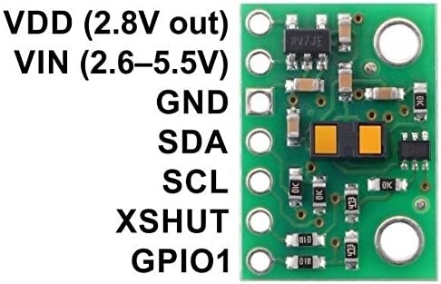
The sensors pinout looks like this:

With VIN the sensor will receive an input voltage and with GND the sensor gets grounded. The line designated as SDA (serial data) is the data line over which the actual data is transmitted. The SCL (serial clock) line is also called the clock line and specifies the clock frequency.
With the XSHUT, you can manually access the sensor, either turn it off or turn it on. This pin is an active-low shutdown input; the board pulls it up to VDD to enable the sensor by default. Driving this pin low puts the sensor into hardware standby. This input is not level-shifted.
Operating principle
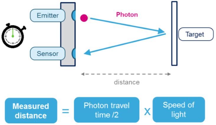
Photons, also light quanta or light particles, are vividly said the energy "packets" of which electromagnetic radiation consists. Physically, the photon is considered an exchange particle. One sends a photon quasi loose at the emitter, takes for this a start time, this is reflected and caught again at the sensor. This results in a time-of-flight or run-time measurement. Since we know the speed of light, we can calculate the distance. The distance to our measured object is half of this distance, because one has completed a way there and back.
There is already a driver for the VL53L1X:

However, we want to adapt this one a bit more to our style. (Just for practice, not for punishment.)
Wiring it to the Raspberry Pi
At the next point we will wire it like follows to the Raspberry Pi:
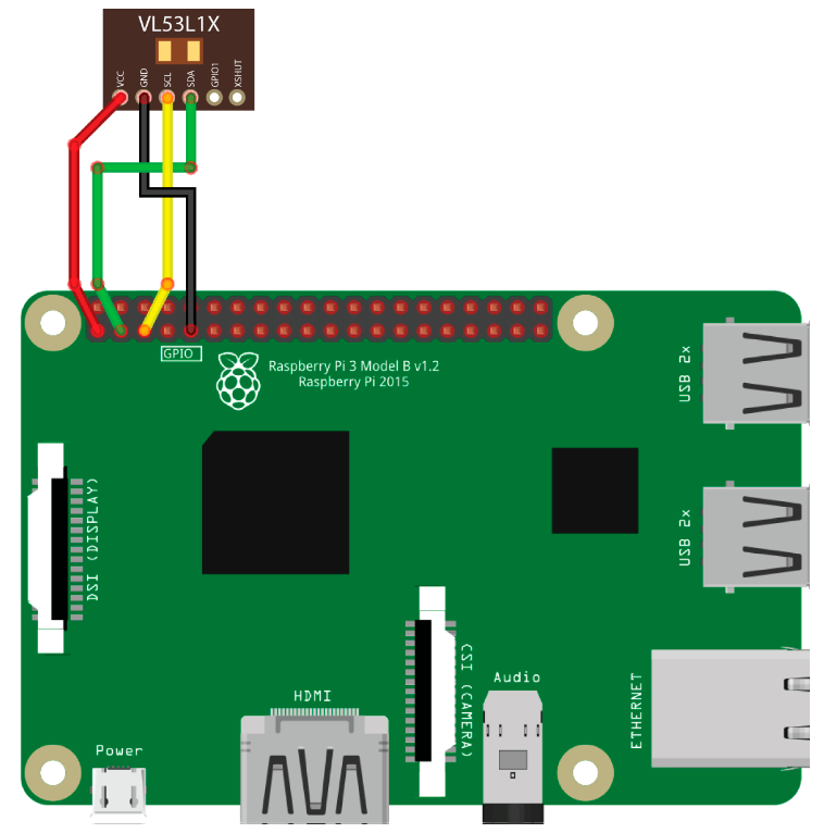
From pin 1 (5V) of the Raspberry Pi we go directly to VIN or VCC of the VL51L1X. This is labeled differently depending on the manufacturer. To ground the sensor, we connect the GND of the sensor to pin 9 (GND). On the Raspberry Pi, an I2C bus is enabled by pin 3 (SDA) and pin 5 (SDC). We now connect SDA to SDA and SCL to SCL.
This results in the following constellation:
Raspberry Pi |
VL53L1X |
Pin 1 (5V) |
VIN or VCC |
Pin 3 (SDA) |
SDA |
Pin 5 (SCL) |
SCL |
Pin 9 (GND) |
GND |
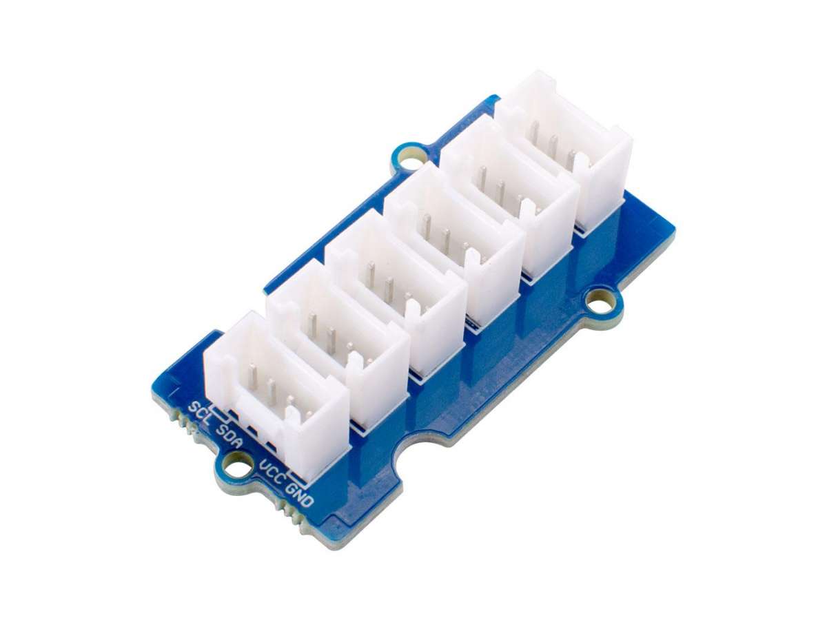
Alternatively you can use an I2C Hub and connect the Raspberry Pi with Female Jumper to Grove Wires. Depending on the pins of the sensor you have to connect Female Jumper to Grove to the hub or Male Jumper to Grove. This makes it possible to use multiple I2C devices at the same time.
An I2C Hub looks as example like this:
Alternatively also an I2C Hat could be used:
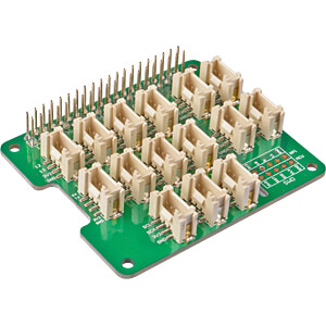
Preparations on the Raspberry Pi
Activating the I2C bus with raspi-config
To enable I2C we have to activate the interface in the kernel. This can easily be done with the Raspberry Pi configuration tool raspi-config.
sudo raspi-config
In the interface we navigate to Advanced Options - I2C.
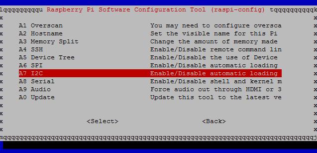
Pressing the Enter key activates I2C. You are asked if you want to activate the ARM I2C interface and if the I2C kernel module should be loaded automatically at system start. We confirm both with Yes.
In addition, the configuration tool points out that the settings only become active after a reboot and offers to reboot the system now. We also confirm this with Yes and restart the system. In principle, I2C is now enabled on the Raspberry Pi.
Manually activating the I2C bus
The following also explains how to manually enable the serial bus interface on the Pi and make it usable.
To manually enable I2C on the Raspberry Pi we need to load the I2C kernel module at boot time. For this we edit the file /etc/modules.
sudo nano /etc/modules
We enter the I2C kernel modules into the file and then save the file.
i2c-bcm2708
i2c-dev
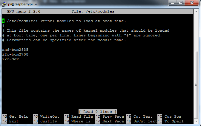
Furthermore the file /boot/config.txt can be opened and checked for the correct content.
sudo nano /boot/config.txt
You should find the following two lines at the end of the file. Otherwise we add them and save and close the configuration file.
dtparam=i2c1=on
dtparam=i2c_arm=on
Finally we edit the file /etc/modprobe.d/raspi-blacklist.conf. This file contains modules which are not loaded during operation, i.e. no entries for I2C may be contained here. The following lines must not be in the file or must be commented out by prepending the # character per line so that I2C becomes active.
# blacklist spi and i2c by default
# blacklist spi-bcm2708
# blacklist i2c-bcm2708
After we have manually made the settings to enable I2C on the Raspberry Pi, the single board computer must be rebooted for the settings to become active.
sudo reboot
Testing the I2C bus
After we have activated the I2C interface on the Raspberry Pi using raspi-config or manually, we can test if it works. With the help of the tool i2cdetect, the serial bus is scanned for connected devices, such as sensors or similar. In a table the connected devices become recognizable. For this we first install the I2C toolkit.
sudo apt-get install i2c-tools
sudo i2cdetect -y 1
Also install smbus for python2 (there are other libraries available but I haven’t looked into them yet)
sudo apt-get install python-smbus
or for python3
pip3 install smbus2
Installing the VL53L1X library
In the next step you can install the library for the sensor with:
sudo pip3 install vl53l1x
Programming the distance measurement
Here we can refer to the following example:
import VL53L1X

# Open and start the VL53L1X sensor.
# If you've previously used change-address.py then you
# should use the new i2c address here.
# If you're using a software i2c bus (ie: HyperPixel4) then
# you should `ls /dev/i2c-*` and use the relevant bus number.
tof = VL53L1X.VL53L1X(i2c_bus=1, i2c_address=0x29)
tof.open()

# Optionally set an explicit timing budget
# These values are measurement time in microseconds,
# and inter-measurement time in milliseconds.
# If you uncomment the line below to set a budget you
# should use `tof.start_ranging(0)`
# tof.set_timing(66000, 70)

tof.start_ranging(1)  # Start ranging
                      # 0 = Unchanged
                      # 1 = Short Range
                      # 2 = Medium Range
                      # 3 = Long Range

# Grab the range in mm, this function will block until
# a reading is returned.
distance_in_mm = tof.get_distance()

tof.stop_ranging()
As you can see, there are the following 3 modes:
Mode name |
Number |
Distance |
Short |
1 |
136cm |
Medium |
2 |
290cm |
Long |
3 |
360cm |
We learned how a ToF sensor works, how to allow the I2C bus and how to connect an I2C device to the Raspberry Pi. We don't need to develop a formula for measuring the distance, because we can already use an existing library for our driver here.
In the next chapter, we'll look at Speed measurement with ToF sensor VL53L1X (Python).
