Contents
ipa_calibration
Code at https://github.com/ipa320/ipa_calibration.
Overview
The ipa_calibration project contains packages that allow for optimizing uncertain extrisic transforms within a robot's kinematic tree. The project contains out of five packages:
- ipa_calibration_interface
- jointstate_saver
- libcalibration
- relative_localization
- transfer_calibration
The ipa_calibration_interface package contains full implementations of the calibration_interface class for several robots (rob@work, squirrel robotino, care-o-bot 4) which is provided by the libcalibration package. Furthermore, it provides nodes for detecting checkerboards and pitags in the environment utilizing a suitable rgb camera of the robot. The cameras that are being used in the process have to be calibrated beforehand. This package can fully be replaced by an other one that implements the calibration_interface class and provides all other methods to move the robot or parts of it and detect the transforms needed and publishes them to TF. For further information take a look at the section about this topic.
The jointstate_saver package is not part of the actual calibration routine. It allows the user to capture joint states of cameras or arms of the robot to build collision-free trajectories that can be used for the calibration routine afterwards.
The libcalibration package contains all the necessary code to optimize uncertain transforms and save the results to the drive. The package provides an abstract calibration_interface class that can be derived from the user to set up a calibration routine for custom robots. All necessary transforms for the calibration process have to be available from TF in order to be usable.
The relative_localization package provides methods to set up a reference coordinate system in the environment which can be used in the calibration process when markers are attached to the environment. It also provides an orientation to which the robot's base can be moved against. There are two options provided, building a reference coordinate system by either using a corner of two walls or a box. The packages makes use of the laserscanners of a robot, which have to be calibrated beforehand.
The transfer_calibration packages contains code in order to move the calibration results from its source file to a destination file and replace the corresponding parameters in there. However, the package in no longer maintained and parameters should be updated manually.
Creating a custom calibration interface package
The libcalibration package provides a general interface class (calibration_interface) which has to be implemented for each robot that is going to be used for calibration. The interface provides the following methods:
1 virtual bool moveRobot(int current_index) = 0;
This method is called by the robot_calibration.cpp whenever the robot shall do its next move, the current_index parameter is a counter that counts upwards in a loop with before every call of moveRobot().
1 virtual int getConfigurationCount() = 0;
The method is called in a loop within robot_calibration.cpp in order to find out how often to execute moveRobot()
1 virtual void preSnapshot(int current_index) = 0;
Snapshots of all relevant TF transforms will be done by robot_calibration.cpp after having successfully executed moveRobot(). Before those snapshots will be taken, preSnapshot() will be called with the index of the current configuration that was executed in moveRobot() before. This methods gives the user the chance to execute some code before any snapshot happens (e.g. wait for transforms that have to be detected to be updated in TF, wait to mitigate shaking effects in robot's kinematic after moving, etc...)
This method will be called at the end of the calibration routine, when the uncertain transforms are calculated. The pattern points (in 3 dimensions) of each marker relative to the marker's local frame needs to be stored to the pattern_points_3d parameter. The name of each marker (marker_frame) will be passed over to the method and therefore markers can have different patterns, hence one can mix pitags, checkerboards, etc... Ensure that static and detected frames of the same marker have the same pattern.
This method will be called during the initialization process of a RobotCalibration object, so it can be set up correctly. The user has to pass over the corresponding values. Parameter description:
uncertainties list: It has to be set up like this: [parent frame, child frame, parent marker frame, child marker frame]
optimization_iterations: Iterations of the optimization loop
transform_discard_timeout: Time after which a transform (of detected markers) in TF will be considered outdated and won't be used in the calibration process anymore
calibration_storage_path: Path where the results of the calibration will be stored to
The method will be called at the end of a calibration process when storing the results to the given calibration_storage_path (see getCalibrationSettings()). It is used to generate a filename for the output files of the results. Two files will be created, the file with the calibration results and an other one which holds all relevant TF transforms in order to perform an offline calibration without being connected to the robot. In order to trigger the offline calibration the load_data flag has to be set to true when creating a RobotCalibration object. But the offline calibration has its limits, one can only swap the order of the uncertain transforms but can't calibrate new ones. For the results file, the appendix is set to "results" and for the offline data it is "offline_data". The results file can have a user-defined file extension, therefore file_extension is true, but the offline data it is forced to .txt so don't add a file extension by yourself here (file_extension equals false).
In order to start the calibration, one has to create a RobotCalibration object inside a try-catch block:
The parameter &nh is the address to the node handle of the current ros node, interface is a pointer to the interface instance that has been created beforehand and load_data specifies whether to perform an offline calibration or not. Do not forget to include following headers:
Take a look at ipa_calibration_interface/ros/src for examples about how to set up everything (camera_laserscanner_calibration_node.cpp and camera_arm_calibration_node.cpp).
IPA Calibration Interface
The ipa_calibration stack offers a full implementation of a calibration interface package called ipa_calibration_interface which provides interfaces for different robot types that are relevant at the Fraunhofer IPA. Such robots are rob@work, care-o-bot and squirrel robotino. The package also comes along with two detection methods in order to detect pitags and checkerboards in the environment.
Camera-Laserscanner Calibration
This type of calibration makes use of cameras and laserscanners of the robot in order to calibrate extrinsic transforms. The robot and its cameras will be moved around to capture data from different positions and angles. The routine makes use of the relative_localization package in order to set up a reference frame for robot movement and marker placement.
Requirements
- Packages:
Please install the cob_object_perception repository and its dependencies to enable pitag detection
Optional: For a working simulation with the robotino robot install the needed repositories from the squirrel-project into your catkin workspace
git clone https://github.com/squirrel-project/squirrel_robotino.git
and follow the installation instructions from the squirrel_robotino repository. Check the Simulation section for further details.
Printed markers (checkerboards or pitags). Some markers can be found in the ipa_calibration/ipa_calibration_interface/common/files folder.
Setting up the calibration environment
Before calibrating the robot one has to select an appropriate place for attaching some markers in the environment. The localization of the robot in this environment will be done using the relative_localization package. This package offers two ways for localizing the robot, the box detection and the corner detection which both utilize the laserscanners of the robot in use. In either case, the front wall has to be detected. That wall is the one the robot is facing, so ensure that the x-axis of the chosen base_frame (see yaml files) is pointing towards the wall and that the front wall normal does not span an angle over 45° with that x-axis, otherwise the front wall won't be detected anymore. That means that the robot's base should not be rotated too much during the calibration process.
Box detection
This method requires a flat wall segment, i.e. there should not be any objects around. In the center of this wall segment place a small box, which is higher than the laser scanner mounting height and which has to touch the wall. The box must stand apart from the wall by more than 10 cm. The box is used to localize the calibration pattern with the laser scanner. Similarly, place robot somwhere at the center of the wall segment facing the box with its laser scanner.
The search algorithm will use all laserscanner points within the defined box_search_polygon to find the box. The other points inside the front_wall_polygon contribute to finding the front wall.
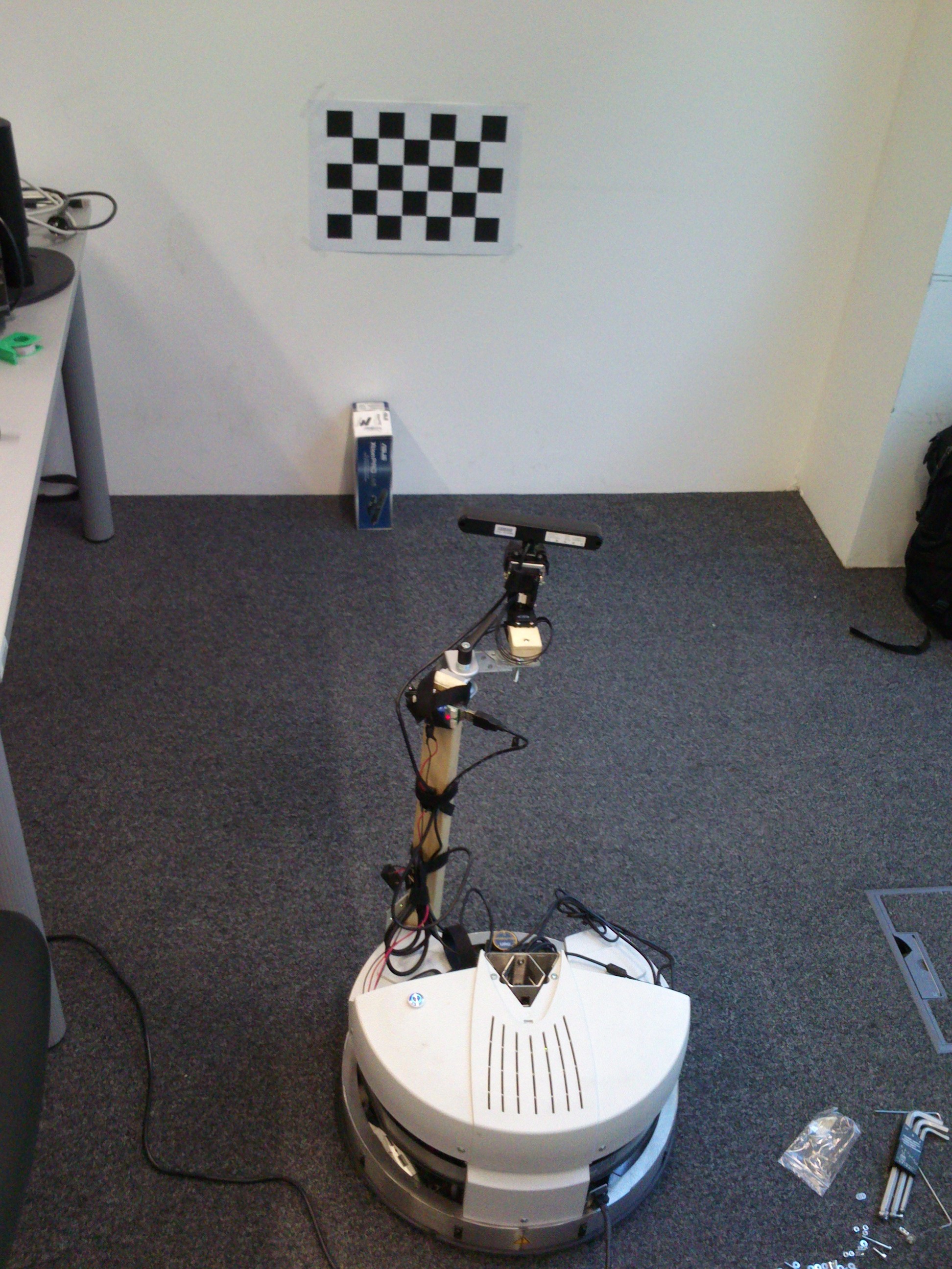
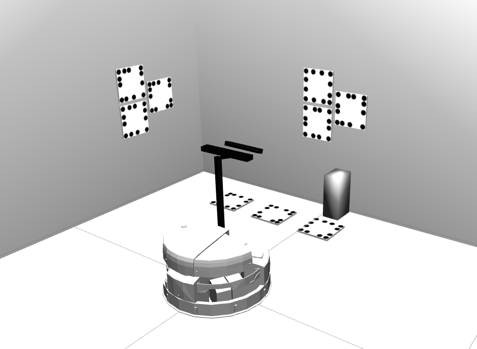
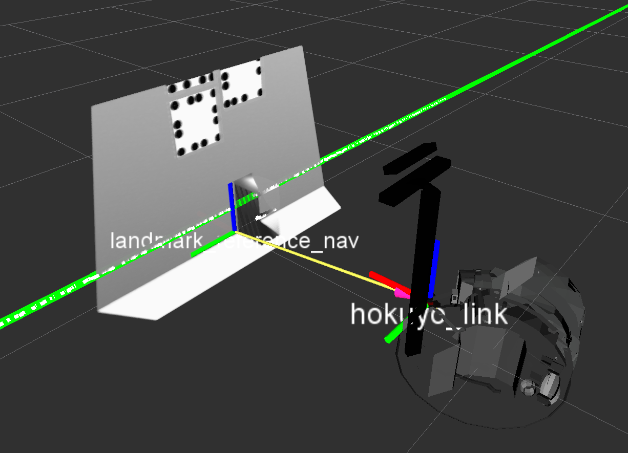
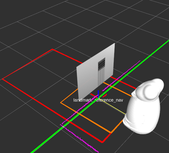
The setup should look similar to the following examples. The last image visualizes the reference coordinate system (here: landmark_reference_nav) which has the same orientation as the base link of the robot and which is located at the intersection of the left box edge and the wall at ground level.
There are some properties you may want to edit in order to match your calibration environment well. These properties can be found in the ipa_calibration/relative_localization/ros/launch/settings/box_localization_params_ROBOT.yaml file.
# Defines how fast new measurements are averaged into the transformation estimate (new_value = (1-update_rate)*old_value + update_rate*measurement). [0,1]
# double
update_rate: <update_rate>

# The name of the computed reference frame.
# string
reference_frame: <ref_frame>

# height above ground of base frame
# double
base_height: <base_height>

# Chosen base link of robot that is used to build the reference frame upon.
# string
base_frame: <base_link>

# frame which is used to filter out wall points, it can be assigned with an existing frame or a yet unknown frame
# Existing frame: Polygons for detection wall points will be build upon the assigned existing frame (e.g. robot's base)
# Unknown frame: A new frame will be generated at startup upon the first reference_frame detection (from reference_frame to base_frame)
# The frame will be set up once at startup and stays fixed from that time on which prevents that robot rotations mess up the reference frame detection.
# string
polygon_frame: <polygon_frame>

# laser scanner topic
# string
laser_scanner_topic_in: <laser_topic>

# Polygon points that define the closed area which is used to find the front wall inside.
# Includes x and y coordinates [in m] of each point that define the polygon in the robot's base frame. Input at least 4 points for a closed region. Do not forget to repeat the first point at the end.
# Relative to polygon_frame
# vector<Point2f>
front_wall_polygon: [X1, Y1,
                     X2, Y2,
                     X3, Y3, ...]

# Polygon points that define the closed area which is used to find the box inside.
# Includes x and y coordinates [in m] of each point that define the polygon in the robot's base frame. Input at least 4 points for a closed region. Do not forget to repeat the first point at the end.
# vector<Point2f>
box_search_polygon: [X1, Y1,
                     X2, Y2,
                     X3, Y3, ...]

# Example of a closed polygon
box_search_polygon: [0.3, 0.5,
                     1.5, 0.5,
                     1.5, -0.5,
                     0.3, -0.5,
                     0.3, 0.5]
One has to define polygons which will be used to reliably detect the reference coordinate system. The image above shows an example of those polygons, the front_wall_polygon is shown in red whereas the box_search_polygon is shown in orange. The visualization of the polygons will be published in a Marker-topic and can be viewed using Rviz. Those polygons can have their own polygon_frame which will be spawned once at startup relative to the detected reference_frame using the given base_frame of the robot as initialization. However, this will only happen when the polygon_frame does not already exist in TF or is outdated. This feature allows that the polygons stay at a fixed position independent from robot movement.
Corner detection
This approach localizes the robot against a corner of two perpendicular walls. Ensure that there are no objects around that corner (in a 2-3 m range) because they could interfere with the correct localization of the corner. The robot should be placed facing one of these walls, as you can see in the following images. The second image visualizes the reference coordinate system which has the same orientation as the base link of the robot and which is located at the intersection of the two walls at ground level.
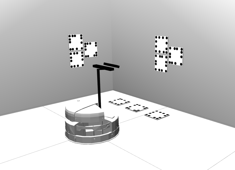
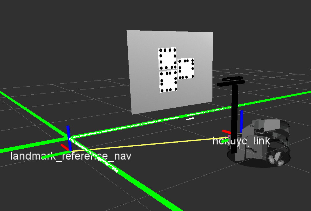
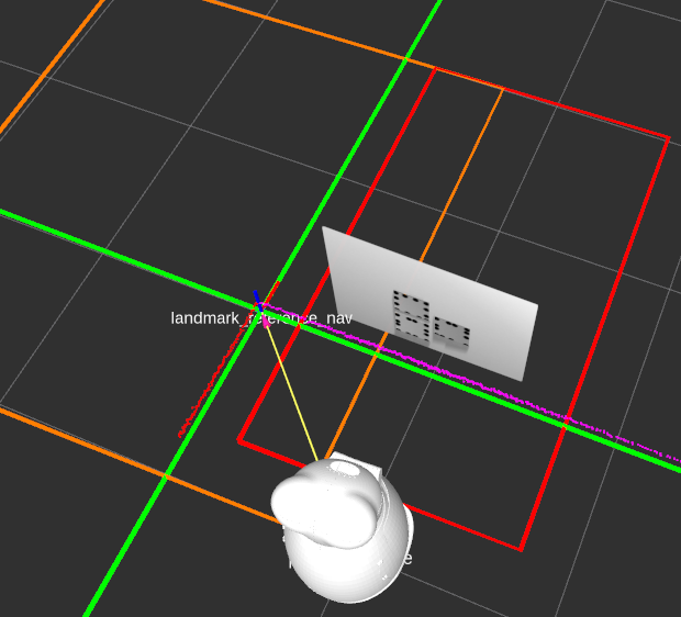
The search algorithm will use all laserscanner points within the defined side_wall_polygon to find the side wall. The other points inside the front_wall_polygon contribute to finding the front wall. The software automatically picks the frontal wall first and then seeks the best fitting perpendicular line resulting from the side_wall_polygon laserscanner points.
There are some properties you may want to edit in order to match your calibration environment well. These properties can be found in the squirrel_calibration/relative_localization/ros/launch/settings/corner_localization_params_ROBOT.yaml file
# Defines how fast new measurements are averaged into the transformation estimate (new_value = (1-update_rate)*old_value + update_rate*measurement). [0,1]
# double
update_rate: <update_rate>

# The name of the computed child frame.
# string
reference_frame: <ref_frame>

# height above ground of base frame
# double
base_height: <base_height>

# Chosen base link of robot that is used to build the reference frame upon.
# string
base_frame: <base_link>

# frame which is used to filter out wall points, it can be assigned with an existing frame or a yet unknown frame
# Existing frame: Polygons for detection wall points will be build upon the assigned existing frame (e.g. robot's base)
# Unknown frame: A new frame will be generated at startup upon the first reference_frame detection (from reference_frame to base_frame)
# The frame will be set up once at startup and stays fiixed from that time on which prevents that robot rotations mess up the reference frame detection.
# string
polygon_frame: <polygon_frame>

# laser scanner topic
# string
laser_scanner_topic_in: <laser_topic>

# Polygon points that define the closed area which is used to find the front wall inside.
# Includes x and y coordinates [in m] of each point that define the polygon in the robot's base frame. Input at least 4 points for a closed region. Do not forget to repeat the first point at the end.
# Relative to polygon_frame
# vector<Point2f>
front_wall_polygon: [X1, Y1,
                     X2, Y2,
                     X3, Y3, ...]

# Polygon points that define the closed area which is used to find the side wall inside.
# Includes x and y coordinates [in m] of each point that define the polygon in the robot's base frame. Input at least 4 points for a closed region. Do not forget to repeat the first point at the end.
# Relative to polygon_frame
# vector<Point2f>
side_wall_polygon: [X1, Y1,
                    X2, Y2,
                    X3, Y3, ...]
One again has to define polygons that are used to detect the reference frame reliably. The image above shows the front_wall_polygon in red and the side_wall_polygon in orange. Take a look at the Box Detection section for more information about polygons.
Placing markers
After having decided for a detection method one has to attach markers to the environment. Markers can either be checkerboards or pitags. Each marker that has been placed needs to to be added as static TF transform in its respective setup launch file (pitag_setup.launch or checkerboard_marker.launch) so it can be loaded at startup. The position of each marker has to be manually measured relative to the reference frame which will be created by the detection method. It is recommended that the static frames are aligned (rotation and position) the same way as their counterparts that are going to be detected by the cameras.
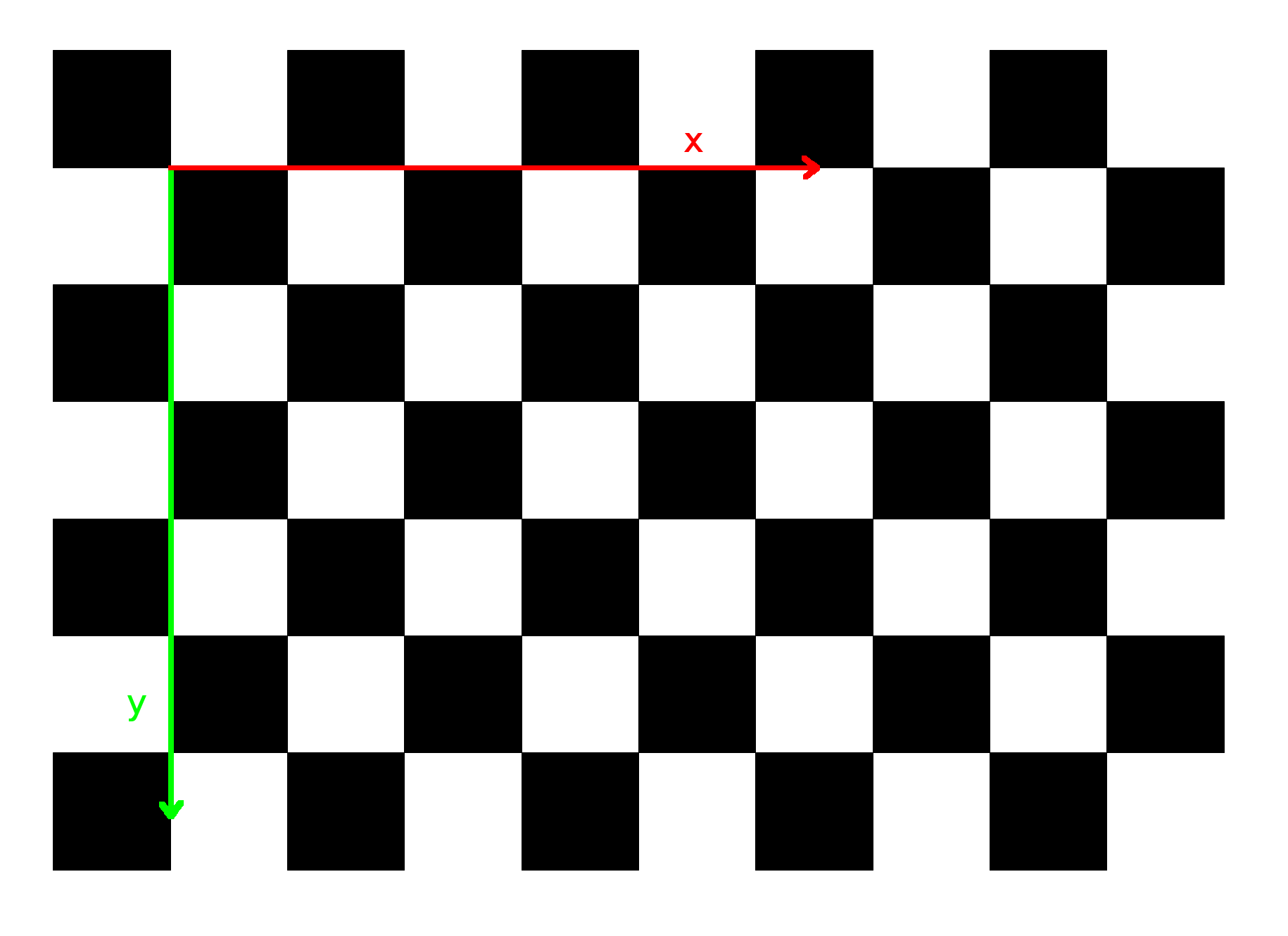
The Checkerboard frame image shows how the internal frame of the checkerboard is aligned. The origin is located at the second cell on the diagonal. Ensure that the detected and the static frames are as aligned the same way. The x-axis of the checkerboard (red) is going from left to right and the y-axis (green) is pointing downwards. The z-axis is pointing into the plane.
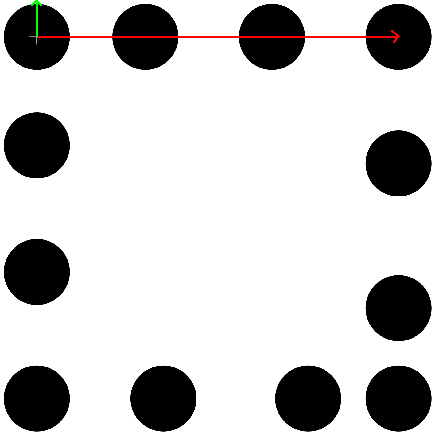
The Pitag frame image shows how the internal frame of a pitag is aligned. The x-axis (red) is pointing from left to right while the y-axis (green) is pointing upwards. The z-axis is pointing out of the plane. The origin is located at the circle with the cross inside.
Setting up the calibration parameters
camera_laserscanner_calibration.launch: This is the main launch file to run this type of calibration which resides in the ipa_calibration/ipa_calibration_interface/ros/launch folder. The file will set up the marker setup, start the marker detection and execute the calibration routine afterwards utilizing the cameras and the laserscanners of the robot. Launch command:
roslaunch ipa_calibration_interface camera_laserscanner_calibration.launch robot:=<robot> marker:=<marker> reference:=<reference> load_data:=<load_data>
Parameters:robot: Specifies the robot that is used so the correct yaml files will be loaded. So far there are two functional robots implemented, the squirrel robotino (robot:=robotino) and the RAW3-1 (robot:=RAW). In future there will be the care-o-bot (robot:=cob) supported as well.
marker: Determines which marker setup will be loaded. Currently there are two marker types, pitags (marker:=pitag) and checkerboards (marker:=checkerboard).
reference: Determines how the reference frame will be set up, either using a corner (reference:=corner) or a box (reference:=box).
load_data: Starts the offline calibration of the last calibration results.
calibration_settings folder: The calibration_settings folder contains all necessary information for the calibration routine to work for each robot. It can be found in the ipa_calibration/ipa_calibration_interface/ros/launch folder. Each of the included files has several settings:
cameras_list: [camera1_name, camera1_dof, camera1_max_delta_angle,
               camera2_name, camera2_dof, camera2_max_delta_angle, ...]
List of cameras invloved in the calibration process.
cameraX_name can be any name to distinguish different cameras inside the interface methods.
max_delta_angle is a security measure to avoid movement when target angles and current angles of a camera are not too far away from one another. This can lead to collision issues for some cameras (e.g. when attached to an arm). Setting it to 0 turns it off (only recommended for pan/tilt cameras)
E.g: cameras_list: ["kinect_front", "2", "0"]
The example cameras_list shown above has one camera called "kinect_front" which has two degrees of freedom (pan/tilt) and does not use the max_delta_angle security measure.

x_range: [x_start, x_step, x_end]
y_range: [y_start, y_step, y_end]
phi_range: [phi_start, phi_step, phi_end]
These range parameters generate poses for the robot's base to feed the base configuration vector. A grid will be generated using the start, step and end values of each parameter.
During the calibration snapshot process those base configurations will be used to move the robot around. The values are measured relative to the reference_frame frame which will be set up by the relative_localization package and is similarly aligned like the chosen base_frame in the relative_localization package.
The phi angle describes the desired rotation of the base_frame in relation to the reference_frame. The rotation axis is assumed to be the z-axis.

base_configs: [x_1, y_1, phi_1,
               x_2, y_2, phi2, ...]
Instead of using the range parameters above one can directly place the wished base poses in here. The base_configs parameter has priority over the range parameters, which means if it is not empty it will be used over the range parameters. The values are also relative to the detected reference_frame.

camera1_name_ranges: [dof1_start, dof1_step, dof1_end,
                      dof2_start, dof2_step, dof2_end, ...]
For each camera in the cameras_list it is also possible to define a range based configuration generator. Each DoF of the camera has its own start, step and end value.
The camera and base configurations are connected in a way that first the robot drives to a base configuration and then cycles through all cameras' configurations before moving to a new base configuration.
E.g: kinect_front_ranges: [-1.2, 1.0, -0.2,
                           -0.8, 0.8, 0.0]
In the example, the first three values belong to the pan link and the last three to the tilt link and generates the following grid:
[-1.2, -0.8,
 -1.2, 0.0,
 -0.2, -0.8,
 -0.2, 0.0]

camera2_name_ranges: [...]
It is possible to have more than one camera in use for the calibration process. But in this case one has to set up the marker detection for the other cameras as well.

camera1_name_configs: [dof1_1, dof2_1,
                           dof1_2, dof2_2, ...]
It is also possible for a camera in the cameras_list to define the wished configurations directly instead of having them generated. This setting has priority over its range based counter part.

camera2_name_configs: [...]
It is possible to have range based parameters for one camera and direct configurations for an other one.

base_frame: <base_link>
The robot's base moves until the selected base_frame is correctly aligned relative to the reference_frame as given in the base configurations (generated or manually typed).
This parameter is also needed for a security measures (e.g. check distance from reference frame to base_frame before moving the robot, see max_ref_frame_distance).

reference_frame: <ref_frame>
The name of the detected reference frame. It should match the entry given in the relative_localization yaml files.

controller_frame: <controller_frame>
The controller error (between reference_frame and base_frame) will be transformed in the controller_frame coordinates (only the x- and y-coordinates) before being applied to the motors. Generally, this should match with base_frame. But it can be different when an other frame than the base link of the robot is chosen as base_frame, for instance when the robot's base has to be rotated and is therefore not pointing towards the front wall anymore.

max_ref_frame_distance: <max_distance>
This defines the maximum distance (radius) in meters the reference_frame is allowed to be away from the base_frame. If it is too far away, stop all robot movements.
E.g: max_ref_frame_distance: 2.5

uncertainties_list: [parent frame 1, child frame 1, last parent-branch frame 1,
                     last child-branch frame 1, parent marker 1, child marker 1,
                     parent frame 2, child frame 2, last parent-branch frame 2,
                     last child-branch frame 2, parent marker 2, child marker 2, ...]
This parameter is used to define all the uncertain transforms that shall be calibrated during the calibration process. Each uncertain transform resides on a closed kinematic chain.
Two examples of a kinematic chain with one uncertain transform:
1) detected marker frame < ... < last child-branch frame < ... < uncertainty child frame < uncertainty parent frame < ... < origin > ... > last parent-branch frame > ... > static marker frame
2) detected marker frame < ... < last parent-branch frame < ... < origin > ... > uncertainty parent frame > uncertainty child frame > ... > last child-branch frame > ... > static marker frame
A kinematic chain consists of two branches (called child and parent branch in the code) and an origin which marks the frame where both branches meet each other. The detected marker frame and the static marker frame are the end points of the branches and occupy the same location in the real world.
Each uncertainty entry consists of five parameters:
- parent frame: This is the parent frame of the uncertain transform. It has to always be available from TF.
- child frame: This is the child frame (the very next frame after parent frame in TF) of the uncertain transform. It has to always be available from TF.
- last parent-branch frame: Going from the parent frame downwards in TF, this is the last relevant frame for calibration for this route on the kinematic chain. Only transforms prior to last parent-branch frame will be considered as uncertainty for this kinematic chain. It has to always be available from TF.
- last child-branch frame: Going from the child frame upwards in TF, this is the last relevant frame for calibration for this route of the kinematic chain. Only transforms prior to last child-branch frame will be considered as uncertainty for this kinematic chain. It has to always be available from TF.
- parent marker: Going from the child frame upwards in TF, this is the marker frame we hit on our way.
- child marker: Going from the parent frame downwards in TF, this is the marker frame we hit on our way.
When one has several uncertain transform on the same kinematic chain or there are several markers for one uncertain frame, make sure that each of the entries share the same last child-branch frame and last parent-branch frame so they are added all to the same calibration setup. A calibration setup consists of one kinematic chain holding several matching uncertainties and several markers.
E.g: uncertainties_list: ["base_link", "camera_tower_link", "corner_reference_frame",
                                       "camera_optical_frame", "tag_25", "marker_25",
                          "base_link", "camera_tower_link", "corner_reference_frame",
                                       "camera_optical_frame", "tag_36", "marker_36",

                          "camera_tower_link", "camera_link", "corner_reference_frame",
                                         "camera_optical_frame", "tag_25", "marker_25",
                          "camera_tower_link", "camera_link", "corner_reference_frame",
                                         "camera_optical_frame", "tag_36", "marker_36",

                          "base_link", "arm_base_link", "camera_optical_frame",
                               "corner_reference_frame", "marker_25", "tag_25",
                          "base_link", "arm_base_link", "camera_optical_frame",
                               "corner_reference_frame", "marker_36", "tag_36"]
Kinematic chain of the example:
marker_X < ... camera_optical_frame < ... < camera_link < camera_tower_link < base_link > arm_base_link > ... corner_reference_frame > tag_X
The example shows three uncertainties to be calibrated. One from base_link to camera_tower_link, the second from camera_tower_link to camera_link and the last one from base_link to arm_base_link (this uncertainty does not make any sense here because the laserscanner is normally directly attached to the base_link, but here one can see that some parameters have to be switched because the uncertainty is on the other branch). The first and second transform reside on the same branch of the kinematic chain whereas the last one resides on the other branch of the kinematic chain. Each uncertainty can be calibrated using two markers that have been attached to the environment.
The order of the uncertainty optimization is given by the order the uncertain transforms are entered in to the uncertainties_list. In the example above, the transform from from base_link to camera_tower_link will be optimized first followed by the transform from camera_tower_link to camera_link and finally the transform from base_link to arm_base_link will be optimized. The more uncertain a transform is, the earlier it should be optimized. Each uncertain transform has to be available from TF at startup filled a good initial guess ("measure the transform by hand").

optimization_iterations: <num_iterations>
The value determines the number of iterations used for optimizing the uncertainties that reside on one closed kinematic chain. If it is just one uncertainty to optimize, the value will be set to 1 for the optimization of that uncertainty.
E.g: optimization_iterations: 10000

transform_discard_timeout: <timeout>
This is the timeout value in seconds after which a TF transform will be considered outdated and won't be used for the calibration process anymore. This value is relevant during the snapshot process when all relevant transforms will be captured.
E.g: transform_discard_timeout: 2.0

calibration_storage_path: <storage_path>
The results will be stored within "~/.ros/calibration_storage_path"
E.g: calibration_storage_path: "robotino_calibration/camera_pitag_calibration"
detection_settings folder: The detection_settings folder contains all relevant information about detecting markers. Two marker types can be detected, pitags and checkerboards. The folder is located in the ipa_calibration/ipa_calibration_interface/ros/launch folder.
- Checkerboard detection:
checkerboard_cell_size: <cell_size>
This value determines the side length of the chessboard squares in meters

checkerboard_pattern_size: [X,Y]
This parameter sets the number of checkerboard calibration points (in x- and y-direction), i.e. those points where 4 squares meet

checkerboard_frame: <detected_checkerboard>
This value defines the name of the detected checkerboard frame.

camera_frame: <camera_frame>
This is name of the frame on which the image is based on (mostly the camera frame)

camera_image_raw_topic: <image_raw>
This setting holds the topic of the raw (not rectified) camera image.

camera_info_topic: <camera_info>
This value describes the topic to retrieve the intrinsic parameters from (of the used camera)

number_distortion_parameters: <distortion_params>
This sets the number of the distortion parameters of the used camera model
Minimum value: 0

update_frequency: <frequency>
This parameter defines the update frequency [in Hz] at which the checkerboard detection will be tried to be executed.

update_percentage: <percentage>
This setting defines how much (in percent) of the freshly detected transform will be used to update the TF checkerboard transform.
Range: [0.1, 1.0]
- Pitag detection:
get_fiducials_topic: <get_fiducials>
This is the topic to retrieve the detected fiducial markers from.

update_frequency: <frequency>
See above.
The fiducials have to be set up in the ipa_calibration/ipa_calibration_interface/ros/launch/pi_tag folder.
- Checkerboard detection:
robot_settings folder: This folder contains all necessary information about robot internals (topics manipulating parts of the robot or the robot itself). The folder resides in the ipa_calibration/ipa_calibration_interface/ros/launch folder as well. The user has to set up the needed topics in order to move the robot or parts of it as demanded from the general calibration_interface class. The files in here are therefore robot specific and have no mandatory parameters except for one.
calibration_ID: <ID>
This sets calibration interface ID. It decides which robot's interface to use: 0 - Robotino, 1 - RAW, 2 - COB
Simulation
When you have downloaded and installed the optional repository (check the Requirements section for installation) you can run a new command in the terminal. This command will bring up a simulated robotino robot that can be used to get into the calibration code.
roslaunch robotino_bringup_sim robot.launch robot:=tuw-robotino2 robot_env:=calibration-room marker:=<marker>
Parameters:
robot: Take any of the available robotinos you like
robot_env: This has to be set to calibration-room
marker: This can either be pitag or checkerboard (will also create a box). Depending on the selection the corresponding markers will be created in the calibration-room.
Camera-Arm Calibration
This type of calibration makes use of cameras and arms of the robot in order to calibrate extrinsic transforms. The routine makes use of the checkerboard detection. The robot's base will not be moved around but instead one or more arms will be moved. That does also mean that there is no reference frame being set up. Each arm needs to have a checkerboard attached to it.
Requirements
One or more arms need to have a checkerboard pattern mounted on one of their joints. The following image shows an example of an endeffector holding a checkerboard that can be mounted on top of the gripper frame of a robot's arm.
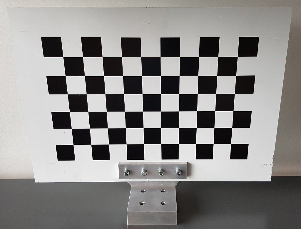
When adding the checkerboard frame as static transform to the checkerboard_marker.launch ensure that it is aligned properly. You find more about that in the Placing markers section of the Camera-Laserscanner Calibration chapter.
Setting up the calibration parameters
camera_arm_calibration.launch: This is the main launch file to run this type of calibration which resides in the ipa_calibration/ipa_calibration_interface/ros/launch folder. The file will set up the marker setup, start the marker detection and execute the calibration routine afterwards utilizing the cameras and the arms of the robot. Launch command:
roslaunch ipa_calibration_interface camera_arm_calibration.launch robot:=<robot> load_data:=<load_data>
Parameters:robot: Specifies the robot that is used so the correct yaml files will be loaded. So far there are two functional robots implemented, the squirrel robotino (robot:=robotino) and the RAW3-1 (robot:=RAW). In future there will be the care-o-bot (robot:=cob) supported as well.
load_data: Starts the offline calibration of the last calibration results.
calibration_settings folder: The folder contains all necessary information for the calibration routine to work for each robot. The folder is located in the ipa_calibration/ipa_calibration_interface/ros/launch folder. Each of the included files has several settings:
cameras_list: [...]
See Camera-Laserscanner Calibration for further details.

arms_list: [arm1_name, arm1_dof, arm1_max_delta_angle,
            arm2_name, arm2_dof, arm2_max_delta_angle, ...]
List of arms invloved in the calibration process.
armX_name can be any name to distinguish different arms inside the interface methods.
max_delta_angle is a security measure to avoid movement when target angles and current angles of an arm are not too far away from one another. Setting it to 0 turns it off (not recommended for arms)

arm1_name_configs: [joint1_angle1, joint2_angle1, joint3_angle1, ...
                    joint1_angle2, joint2_angle2, joint3_angle2, ...]
Arm configurations can only directly be placed in here. There is no automatic generation allowed as with cameras because of collision issues due to several joints invovled.
The arm and camera configurations for this calibration type can easily be captured using the jointstate_saver tool.
Each arm and each camera will be updated on every call to moveRobot during the snapshot process.

arm2_name_configs: [...]
It is possible to have several arms involved in one calibration process. Make sure that there are no collision issues and when there are several cameras as well, you don't get conflicts with one camera detecting markers of an other camera.

camera1_name_ranges: [...]
It is possible to generate configurations for cameras here, but it's not recommended.
Best practice is to capture arm and camera configurations at the same time and place them in here.
See Camera-Laserscanner Calibration for further details.

camera1_name_configs: [dof1_1, dof2_1,
                       dof1_2, dof2_2, ...]
This is the recommended way to integrate camera configurations.
See Camera-Laserscanner Calibration for further detail.

uncertainties_list: [...]
See Camera-Laserscanner Calibration for further detail.

optimization_iterations: <num_iterations>
See Camera-Laserscanner Calibration for further detail.

transform_discard_timeout: <timeout>
See Camera-Laserscanner Calibration for further detail.

calibration_storage_path: <storage_path>
See Camera-Laserscanner Calibration for further detail.
detection_settings folder: The detection_settings folder contains all relevant information about detecting markers. Two marker types can be detected, pitags and checkerboards. The folder is located in the ipa_calibration/ipa_calibration_interface/ros/launch folder. The camera-arm calibration routine can only be used with checkerboards. For more detailed information take a look at the corresponding section in the the camera-laserscanner calibration chapter.
robot_settings folder: This folder contains all necessary information about robot internals (topics manipulating parts of the robot or the robot itself). The folder resides in the ipa_calibration/ipa_calibration_interface/ros/launch folder as well. For more detailed information take a look at the corresponding section in the the camera-laserscanner calibration chapter.
Adding a new robot
It is fairly easy to add new robots to the existing ipa_calibration_interface:
Derive a new interface class from IPAInterface:
   1 #ifndef MY_INTERFACE_H_
   2 #define MY_INTERFACE_H_
   3
   4 #include <ipa_calibration_interface/ipa_interface.h>
   5
   6 class MyInterface : public IPAInterface
   7 {
   8
   9 public:
  10         MyInterface(ros::NodeHandle* nh, CalibrationType* calib_type,
  11                     CalibrationMarker* calib_marker, bool do_arm_calibration,
  12                     bool load_data);
  13         ~MyInterface();
  14
  15         std::string getRobotName();
  16         void assignNewRobotVelocity(geometry_msgs::Twist newVelocity);
  17         void assignNewCameraAngles(const std::string &camera_name,
  18                                    std_msgs::Float64MultiArray newAngles);
  19         std::vector<double>* getCurrentCameraState(const std::string &camera_name);
  20
  21         void assignNewArmJoints(const std::string &arm_name,
  22                                 std_msgs::Float64MultiArray newJointConfig);
  23         std::vector<double>* getCurrentArmState(const std::string &arm_name);
  24
  25 };
  26
  27 #endif
  28
Extend the static method of IPAInterface::createInterfaceByID() with your new interface class and also extend the RobotTypes enum within the ipa_calibration/ipa_calibration_interface/ros/src/ipa_interface.h header file.
- Implement following methods in your new interface class: Furthermore, add all necessary callback functions to retrieve the necessary information and to control the robot movement.
   1 void assignNewRobotVelocity(geometry_msgs::Twist newVelocity);
   2 void assignNewCameraAngles(const std::string &camera_name,
   3                            std_msgs::Float64MultiArray newAngles);
   4 std::vector<double>* getCurrentCameraState(const std::string &camera_name);
   5
   6 void assignNewArmJoints(const std::string &arm_name,
   7                         std_msgs::Float64MultiArray newJointConfig);
   8 std::vector<double>* getCurrentArmState(const std::string &arm_name);
Create new yaml files whereas you can take one of the default ones from the corresponding Default folder as a template. Set up one or more files, depending on how many calibration methods you want to use, for the ipa_calibration/ipa_calibration_interface/ros/launch/calibration_settings folder and add another file for the ipa_calibration/ipa_calibration_interface/ros/launch/robot_settings folder: All the topics and attributes needed for your new interface class should be stored within the yaml file inside robot_settings. The name of this yaml file follows following convention: ROBOT_settings.yaml, choose a reasonable ROBOT tag. This tag will also be used in the main launch files for the calibration types. The settings for the calibration have to be set in the calibration_settings folder. Depending on which type of calibration you want to use you have to create either a camera_arm_calibration_params_ROBOT.yaml file for the Camera-Arm calibration type, a camera_laserscanner_calibration_checkerboard_params_ROBOT.yaml or a camera_laserscanner_calibration_pitag_params_ROBOT.yaml for the Camera-Laserscanner calibration either using a checkerboard or pitags as markers. The Camera-Laserscanner calibration requires another yaml file to be created within the ipa_calibration/relative_localization/ros/launch/settings which can either be box_localization_params_ROBOT.yaml or corner_localization_params_ROBOT depending on how the calibration environment will be set up.
Fill in the yaml files and don't forget to set the correct calibration_ID which corresponds to the numeric value of the RobotTypes enum.
Multi camera systems
The ipa_calibration_interface package does not support different types of markers to be mixed within one calibration setup, so decide either for using checkerboards or pitags. In case you have to use more than one checkerboard, make sure they have the same pattern, otherwise one has to extend the ipa_calibration/ipa_calibration_interface/ros/src/checkerboard_marker.cpp file in order to support different types of checkerboards. When using several similar checkerboards and several cameras at once one has to consider that every camera can detect every checkerboard on sight which can lead to bad results. Take into account, that each camera needs to have its own detection node being started at startup. That means that the pitag_setup.launch or the checkerboard_setup.launch within the ipa_calibration/ipa_calibration_interface/ros have to be extended for every additional camera in use.
Report a Bug
Use GitHub to report bugs or submit feature requests. [View active issues]
