Contents
robotino_calibration
Code at https://github.com/squirrel-project/squirrel_calibration.
Introduction
This package lets you calibrate the mounting position of the Robotino's RGB-D sensor (Asus Xtion).
It will later also feature the possibility to calibrate the arm mounting position against the camera.
Installation Requirements
Please download the following additional repositories into your workspace
git clone https://github.com/ipa320/cob_object_perception.git
git clone https://github.com/ipa320/cob_perception_common.git
and install all dependencies by moving into your catkin workspace (the folder where you type catkin_make) and run
rosdep update
rosdep install --from-paths /src -y -i
Calibrating the RGB-D camera's mounting position
The calibration process needs an external calibration pattern and can be conducted using either one single checkerboard or any number of Pi-Tags. The locations of these markers are determined by a reference coordinate system which is measured via laser scanner and which is located either inside a corner of two perpendicular walls or at the edge of a box located at a wall.
Laser Scanner
This calibration necessitates that the laser scanner is mounted perfectly parallel to the ground and its mounting position must be known as accurately as possible. If the construction does not yet yield accurate enough figures, the following steps might help.
Conduct a laser scanner to base calibration, see README.md at https://github.com/federico-b/squirrel_nav/tree/laser_odom_calibration/laser_odom_calibration.
Measure laser scanner height and put in the number into the properties.urdf.xacro file of your robot which is located, e.g., at squirrel_calibration/robotino_bringup/robots/uibk-robotino/urdf/properties.urdf.xacro. There search for the block:
  <!-- hokuyo mount positions | relative to base_link -->
  <property name="hokuyo_x" value="0.131740483"/>
  <property name="hokuyo_y" value="0.00937244242"/>
  <property name="hokuyo_z" value="0.102"/> <!-- not used, apprx -->
  <property name="hokuyo_roll" value="0.0"/>
  <property name="hokuyo_pitch" value="0.0"/>
  <property name="hokuyo_yaw" value="-0.0536545473"/>
and enter the measure at hokuyo_z. Optimally, you measure your laser scanner height using a level that is shifted downwards a ruler until it becomes visible in the laser scan. Repeat the procedure from below: shifting the level upwards until visible in the laser scan. Take the average of both measured heights.
Reference coordinate system for the laser scanner
The robot must be localized against the environment using its laser scanner. Choose one of the following procedures for establishing a reference coordinate system with the laser scanner. Keep in mind that the reference frame will always be projected down to the base height of the robot (i.e. to match the ground level in order to make it easier to measure the calibration patterns in regard of the reference frame). You can use the base_height offset (see yaml file below) in case the base_frame of your robot is not at ground level.
Box
This method requires a flat wall segment of at least 2.0 m length, i.e. there should not be any objects around. In the center of this wall segment place a small box, which is higher than the laser scanner mounting height and which has to touch the wall. The box must stand apart from the wall by more than 11 cm. The box is used to localize the calibration pattern with the laser scanner. Similarly, place robotino at the center of the wall segment facing the box with its laser scanner.
The search algorithm will use all laserscanner points within the defined box_search_polygon to find the box. The other points inside the front_wall_polygon contribute to finding the front wall.
The setup should look similar to the following examples. The last image visualizes the reference coordinate system landmark_reference_nav which has the same orientation as its parent, the hokuyo laser scanner, and which is located at the intersection of the left box edge and the wall at ground level.
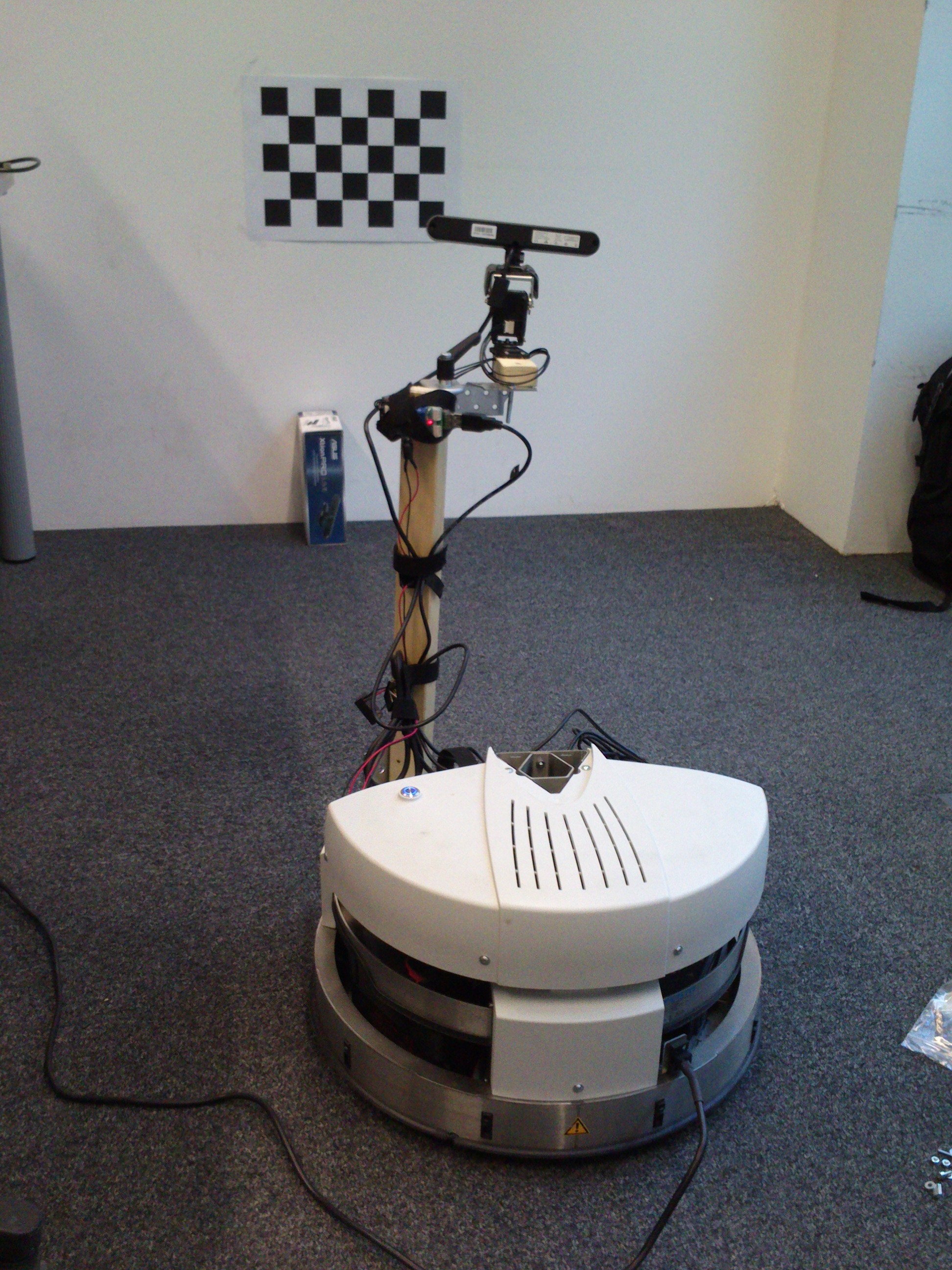
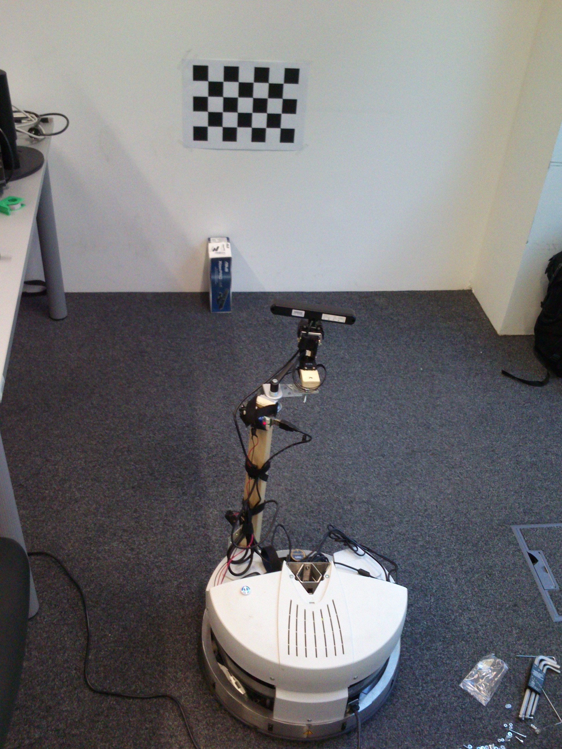
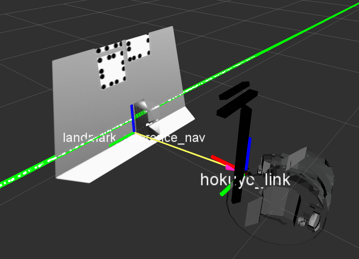
There are some properties you may want to edit in order to match your calibration environment well. These properties can be found in the squirrel_calibration/relative_localization/ros/launch/box_localization_params.yaml file.
# Defines how fast new measurements are averaged into the transformation estimate (new_value = (1-update_rate)*old_value + update_rate*measurement). [0,1]
# double
update_rate: 0.75

# The name of the computed child frame.
# string
child_frame_name: "/landmark_reference_nav"

# the (minimum) length of the frontal wall segment left of the laser scanner's origin (assuming the robot faces the wall), in [m]
# double, deprecated
# wall_length_left: 0.8

# the (minimum) length of the frontal wall segment right of the laser scanner's origin (assuming the robot faces the wall), in [m]
# double, deprecated
# wall_length_right: 0.8

# the maximum +/-y coordinate in laser scan to search for the localization box, in[m]
# double, deprecated
# box_search_width: 0.6

# height above ground of base frame
# double
base_height: 0.0

# base link of robot
# string
base_frame: "base_link"

# laser scanner topic
# string
laser_scanner_topic_in: "/scan"

# Polygon points that define the area which is used to find the front wall inside.
# Includes x and y coordinates [in m] of each point that define the polygon in the robot's base frame. Input at least 3 points.
# vector<Point2f>
front_wall_polygon: [0.3, 0.75,
                     3, 0.75,
                     3, -0.75,
                     0.3, -0.75,
                     0.3, 0.75]

# Polygon points that define the area which is used to find the box inside.
# Includes x and y coordinates [in m] of each point that define the polygon in the robot's base frame. Input at least 3 points.
# vector<Point2f>
box_search_polygon: [0.3, 0.5,
                     1.5, 0.5,
                     1.5, -0.5,
                     0.3, -0.5,
                     0.3, 0.5]
Corner
This approach localizes the robot against a corner of two perpendicular walls. Ensure that there are no objects around that corner (in a 2-3 m range) because they could interfere with the correct localization of the corner. The robot should be placed facing one of these walls, as you can see in the following images. The second image visualizes the reference coordinate system landmark_reference_nav which has the same orientation as its parent, the hokuyo laser scanner, and which is located at the intersection of the two walls at ground level.
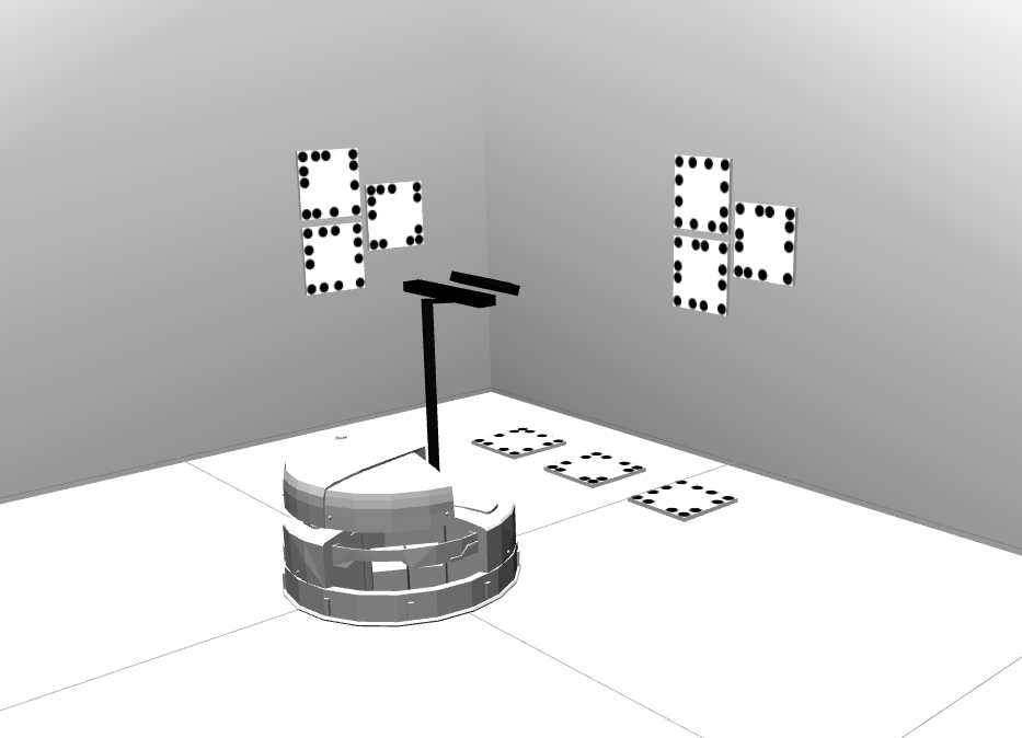
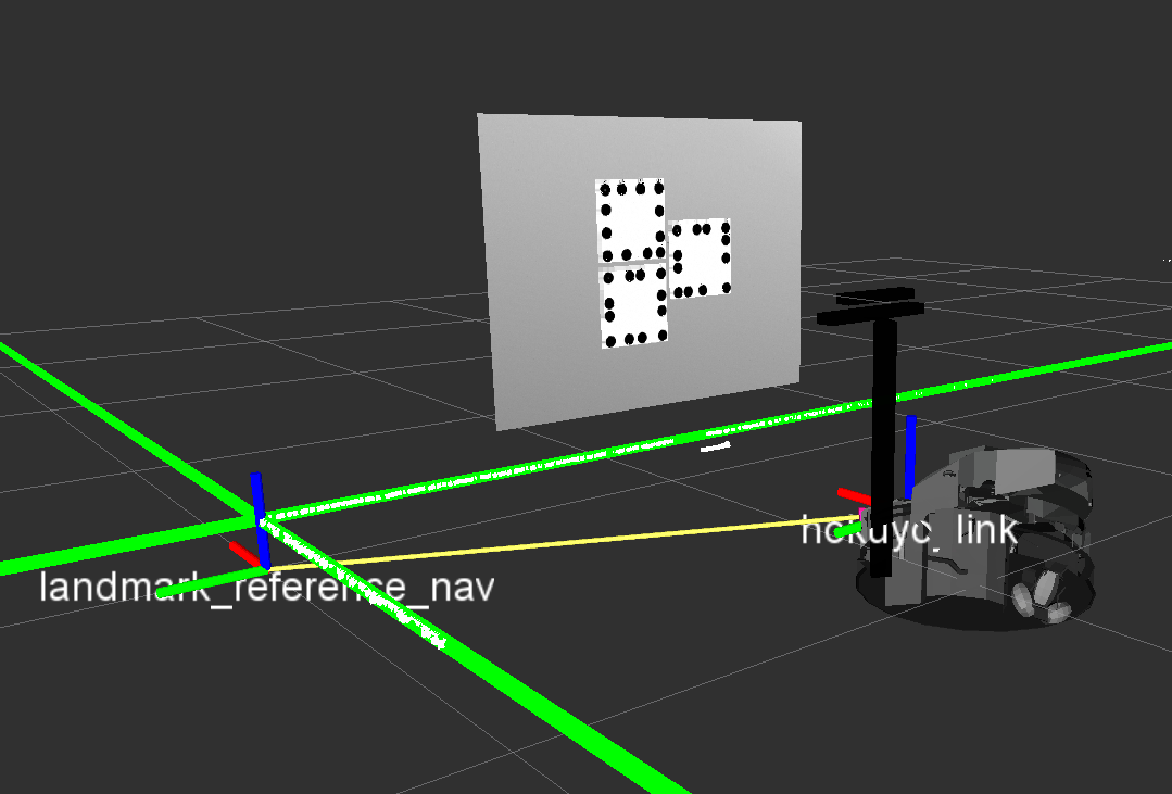
The search algorithm will use all laserscanner points within the defined side_wall_polygon to find the side wall. The other points inside the front_wall_polygon contribute to finding the front wall. The software automatically picks the frontal wall first and then seeks the best fitting perpendicular line resulting from the side_wall_polygon laserscanner points.
There are some properties you may want to edit in order to match your calibration environment well. These properties can be found in the squirrel_calibration/relative_localization/ros/launch/corner_localization_params.yaml file
# Defines how fast new measurements are averaged into the transformation estimate (new_value = (1-update_rate)*old_value + update_rate*measurement). [0,1]
# double
update_rate: 0.25

# The name of the computed child frame.
# string
child_frame_name: "/landmark_reference_nav"

# the (minimum) length of the frontal wall segment left of the laser scanner's origin (assuming the robot faces the frontal wall), in [m]
# double, deprecated
# wall_length_left: 2.5

# the (minimum) length of the frontal wall segment right of the laser scanner's origin (assuming the robot faces the frontal wall), in [m]
# double, deprecated
# wall_length_right: 2.5

# height above ground of base frame
# double
base_height: 0.0

# base link of robot
# string
base_frame: "base_link"

# laser scanner topic
# string
laser_scanner_topic_in: "/scan"

# Polygon points that define the area which is used to find the front wall inside.
# Includes x and y coordinates [in m] of each point that define the polygon in the robot's base frame. Input at least 3 points. Do not forget to repeat the first point at the end.
# vector<Point2f>
front_wall_polygon: [0.3, 0.75,
                     3, 0.75,
                     3, -0.75,
                     0.3, -0.75,
                     0.3, 0.75]

# Polygon points that define the area which is used to find the side wall inside.
# Includes x and y coordinates [in m] of each point that define the polygon in the robot's base frame. Input at least 3 points. Do not forget to repeat the first point at the end.
# vector<Point2f>
side_wall_polygon: [0, 3.0,
                    3.0, 3.0,
                    3.0, 0.3,
                    0, 0.3,
                    0, 3.0]
Mount markers in the environment
Chose one of the following marker types that are used to calibrate the camera. You can find some printout templates for suitable markers at squirrel_calibration/robotino_calibration/common/files/ (checkerboard) or at squirrel_calibration/robotino_calibration_sim/worlds/prefabs/pitags/tagXX (Pi-Tags).
Checkerboard
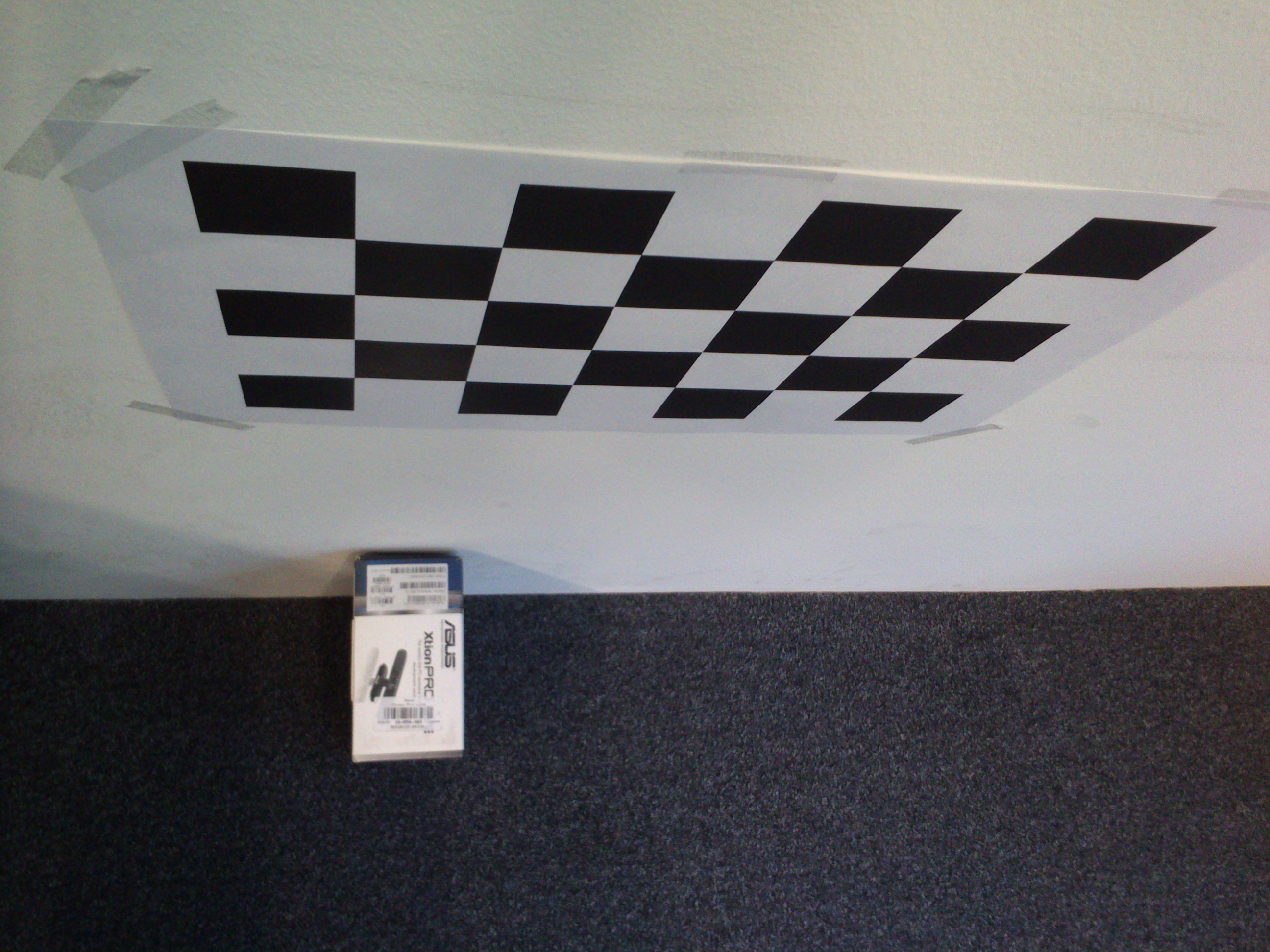
Mount a calibration checkerboard (e.g. from robotino_calibration/common/files/checkerboard_a3_6x4_5cm.pdf in A3 size printed at 100%) horizontally on a wall (use a level to be precise), approximately at the height of Robotino's Kinect (at the moment this is left upper chessboard calibration corner approx. at 80 cm height above ground).
If you are using the box-based localization, you might want to align the box with the leftmost line of checkerboard calibration points (i.e. where 4 squares meet) for simplicity of defining coordinate transformations. Align the left side of the box with the leftmost calibration points. The following images illustrate this setup.
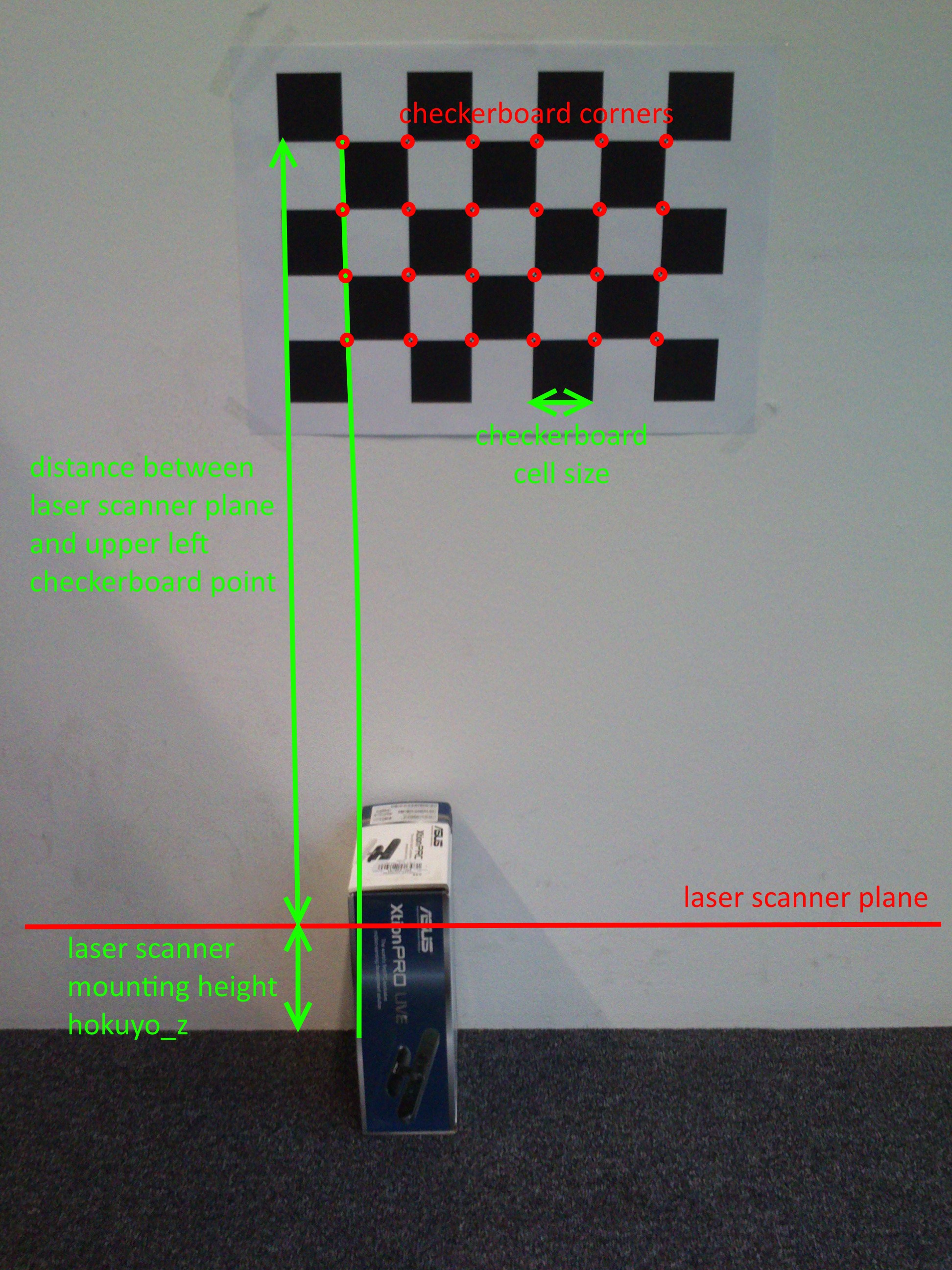
Measure the vertical distance between ground plane and the upper left checkerboard point and insert this number into file squirrel_calibration/robotino_calibration/ros/launch/camera_base_calibration_checkerboard.launch at the line:
<node pkg="tf" type="static_transform_publisher" name="static_transform_publisher_landmark_checkerboard" output="screen" args="0.0 -0.8 0 0 0 0 landmark_reference checkerboard_frame 100"/>
Replace the -0.8 at the y-offset with your measured number in meters. All other numbers should be 0 if the box is aligned with the checkerboard as described above. Use a negative measure because the y-axis of frame landmark_reference is pointing into the ground floor.
Enter the properties of the used calibration pattern (grid size, square side length) into file squirrel_calibration/robotino_calibration/ros/launch/camera_base_calibration_checkerboard_params.yaml at the lines:
### checkerboard parameters
# side length of the chessboard squares
chessboard_cell_size: 0.05
# number of checkerboard calibration points (in x- and y-direction, i.e. horizontal and vertical), i.e. those points where 4 squares meet
chessboard_pattern_size: [6,4]
Pi-Tags
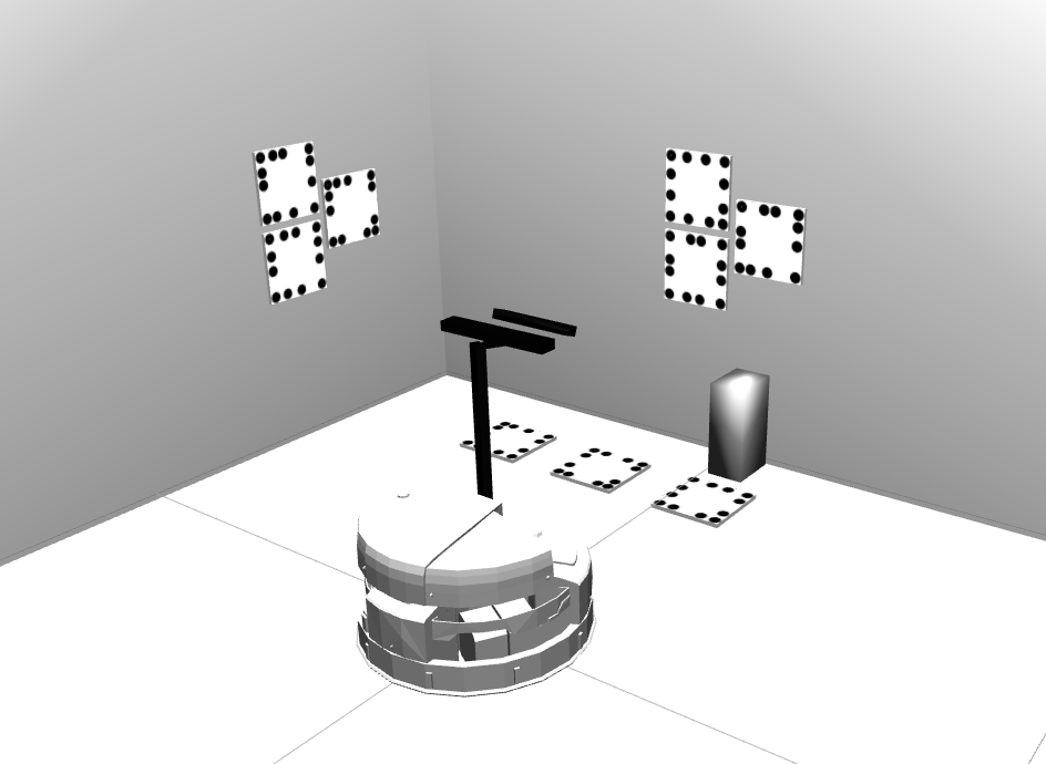
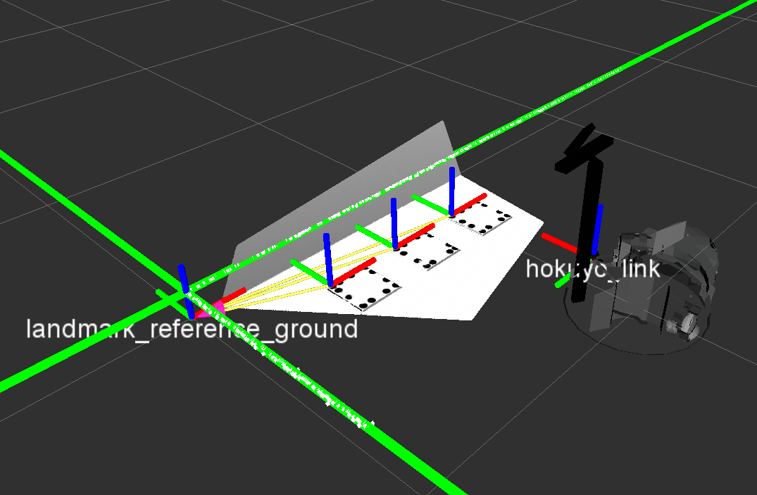
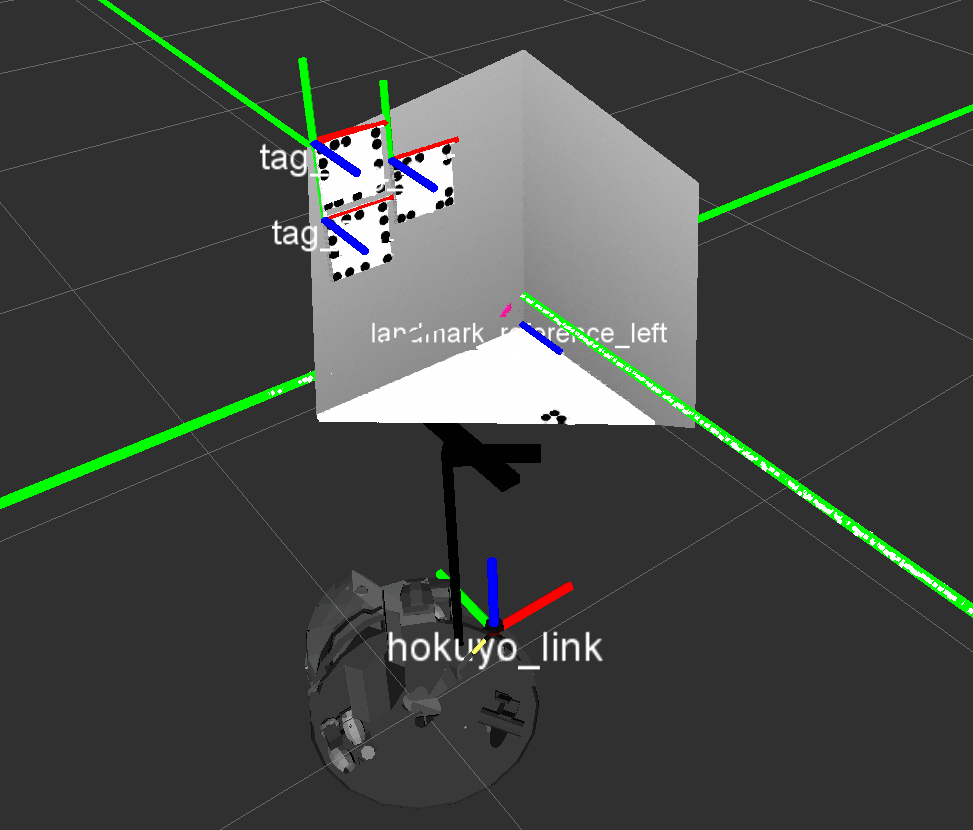
Performing a calibration with Pi-Tags you may place as many tags in your environment as you desire. In the pre-set configuration there are nine tags in total. Three of them have to be placed at the wall in front of the robot, the next triple resides on the floor in front of the robot and the last three tags are located on a wall to the left of the robot. The following picture visualizes this exemplary setup.

To perform a successful calibration it is recommended to align the Pi-Tags to the coordinate systems of the robot, i.e. mount Pi-Tags at the walls parallel to the ground and place Pi-Tags on the ground parallel to the walls, e.g. as depicted above.
Depending on how large you printed the Pi-Tags, you might need to adapt the tags' side length definitions in file squirrel_calibration/robotino_calibration/ros/launch/pi_tag/piTagIni_0.xml. The size of a Pi-Tag is defined as the length between the centers of two neighboring corner points on the edge of a tag. The standard is 0.15 m. You can set the real side length of a tag with the LineWidthHeight attribute:
<FiducialDetector>
        <PI>
                <ID value="25" />
                <!-- Tag size in [m] -->
                <LineWidthHeight value="0.15" />

                <!-- Cross ratios line 0 and 1-->
                <!-- Measurements in % relative to the tag size-->
                <CrossRatioLine0 AB="0.30" AC="0.65" />
                <CrossRatioLine1 AB="0.35" AC="0.75" />

                <!-- Offset for native tag corrdinates -->
                <!-- e.g. position of tag in object centric ccordinate system -->
                <Offset x="0.0" y="0.0" />

                <!-- Rectangle describing the area for sharpness computation in 2d coordinates within the marker plane with respect to the marker origin -->
                <SharpnessArea x="-0.01" y="-0.01" width="0.12" height="0.12"/>
        </PI>
        ...
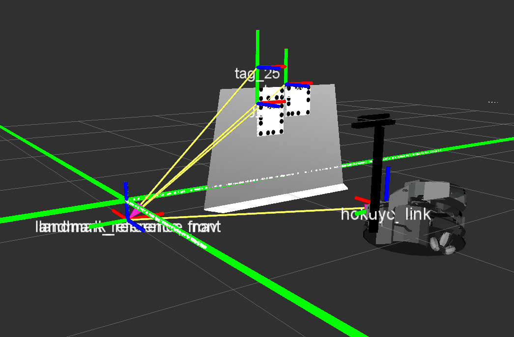
File squirrel_calibration/robotino_calibration/ros/launch/camera_base_calibration_pitag.launch already provides convenient coordinate system definitions if you follow this advice. The defined coordinate systems landmark_reference_front, landmark_reference_left, and landmark_reference_ground are children of the reference system landmark_reference_nav, which originates from the localization algorithm. These coordinate systems are not translated but rotated against landmark_reference_nav in the respective direction of the Pi-Tag orientation at the frontal or left wall, or at the ground.
<node pkg="tf" type="static_transform_publisher" name="static_transform_publisher_landmark_marker_nav_front" output="screen" args="0.0 0.0 0.0 -1.57079632679 0 1.57079632679  landmark_reference_nav landmark_reference_front 100"/>
...
<node pkg="tf" type="static_transform_publisher" name="static_transform_publisher_landmark_marker_nav_left" output="screen" args="0.0 0.0 0.0 0 0 1.57079632679  landmark_reference_nav landmark_reference_left 100"/>
...
<node pkg="tf" type="static_transform_publisher" name="static_transform_publisher_landmark_marker_nav_ground" output="screen" args="0.0 0.0 0.0 -1.57079632679 0 0  landmark_reference_nav landmark_reference_ground 100"/>
These definitions are illustrated further below.
Finally, the real world locations of the mounted Pi-Tags must be entered into squirrel_calibration/robotino_calibration/ros/launch/camera_base_calibration_pitag.launch in relation to a known coordinate frame (this is typically one of the convenience frames landmark_reference_front, landmark_reference_left, or landmark_reference_ground because the tag mounting pose is then just a translation). Please notice that each Pi-Tag position relates to the center of its upper left circle, the one that is marked with a bright cross.
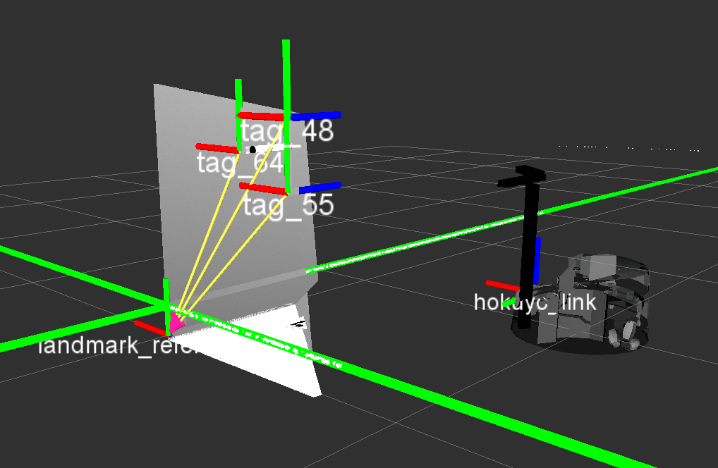
The relative translation of the different tags is visualized in the following images and the respective measured translations that go into file squirrel_calibration/robotino_calibration/ros/launch/camera_base_calibration_pitag.launch are mentioned thereafter.
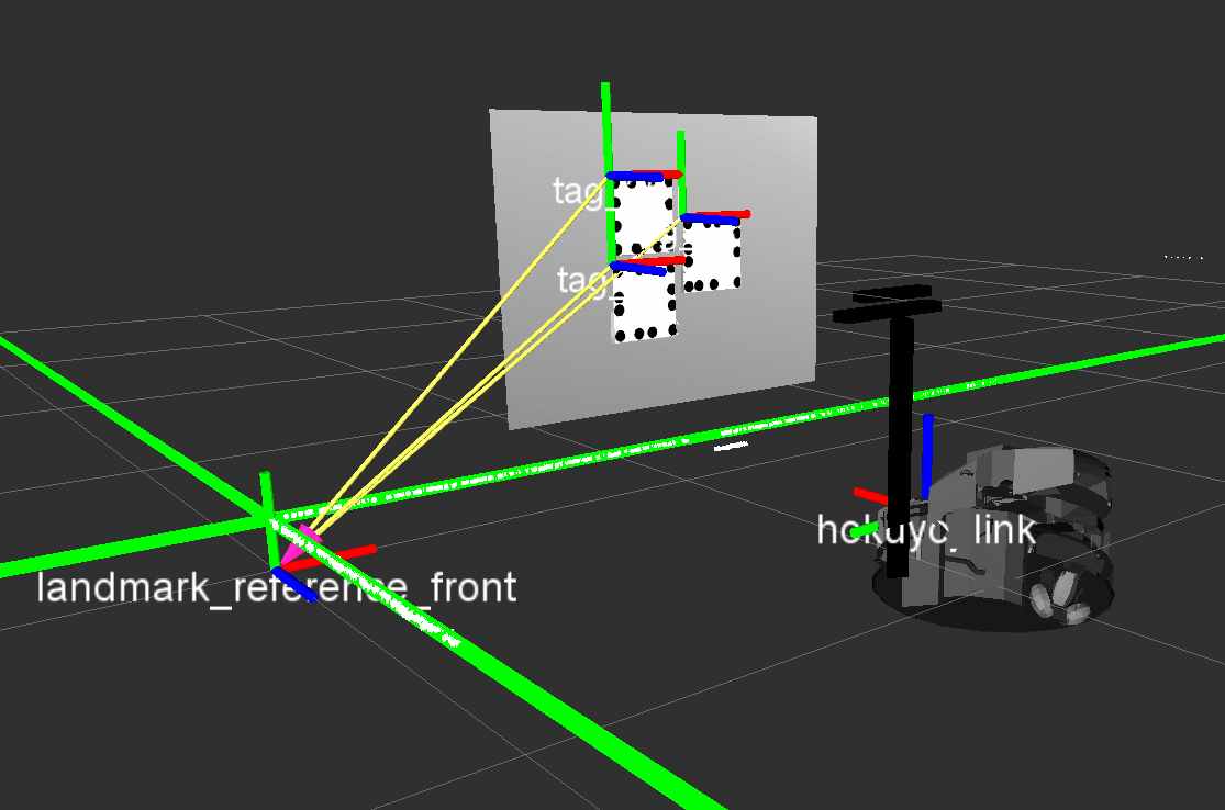
<node pkg="tf" type="static_transform_publisher" name="static_transform_publisher_landmark_tag_25" output="screen" args="0.8 0.75 0.01 0 0 0  landmark_reference_front tag_25 100"/>
<node pkg="tf" type="static_transform_publisher" name="static_transform_publisher_landmark_tag_36" output="screen" args="0.8 0.55 0.01 0 0 0  landmark_reference_front tag_36 100"/>
<node pkg="tf" type="static_transform_publisher" name="static_transform_publisher_landmark_tag_38" output="screen" args="1.0 0.65 0.01 0 0 0  landmark_reference_front tag_38 100"/>
<node pkg="tf" type="static_transform_publisher" name="static_transform_publisher_landmark_tag_48" output="screen" args="-0.6 0.75 0.01 0 0 0  landmark_reference_left tag_48 100"/>
<node pkg="tf" type="static_transform_publisher" name="static_transform_publisher_landmark_tag_55" output="screen" args="-0.6 0.55 0.01 0 0 0  landmark_reference_left tag_55 100"/>
<node pkg="tf" type="static_transform_publisher" name="static_transform_publisher_landmark_tag_64" output="screen" args="-0.4 0.65 0.01 0 0 0  landmark_reference_left tag_64 100"/>
<node pkg="tf" type="static_transform_publisher" name="static_transform_publisher_landmark_tag_69" output="screen" args="0.4 -0.2 0.01 0 0 0  landmark_reference_ground tag_69 100"/>
<node pkg="tf" type="static_transform_publisher" name="static_transform_publisher_landmark_tag_73" output="screen" args="0.7 -0.2 0.01 0 0 0  landmark_reference_ground tag_73 100"/>
<node pkg="tf" type="static_transform_publisher" name="static_transform_publisher_landmark_tag_79" output="screen" args="1.0 -0.2 0.01 0 0 0  landmark_reference_ground tag_79 100"/>
The whole transformation chain from laser scanner to Pi-Tags, e.g. at the frontal wall, is hokuyo_link --> landmark_reference_nav --> landmark_reference_front --> tag_25, which is illustrated below.
Configuration for calibration
 1. Enter the base_frame and the child_frame_name which are needed to ensure the robot is only moving when the reference frame is valid. Also insert the correct camera_optical_frame and checkerboard_frame (Marker_Setup in the image).
2. Insert all transforms (start and end frame) that have to be calibrated in the uncertainties_list. These uncertain transforms have to be entered in the same order as they actually appear in the transformation tree. That means that the first uncertain transform in your tree has to be the first you enter in the uncertainties_list and so on. If we take the example in the image, we had to enter the transform from Robot_Base to Camera_Base first and then add the one from Camera_Base to Camera_Head on top (transforms are marked on green). The order in which those transforms will be calibrated can then be changed in the calibration_order list.
# the robot base frame, needed for security measure (it's the reference frame to check the child_frame against before moving the robot)
base_frame: "base_linkz"

# this is the camera coordinate system which refers to the color image sensor [the transformations between camera_frame and camera_optical_frame should be available from tf]
camera_optical_frame: "kinect_rgb_optical_frame"

# the transformations between base_frame and the first entry of the uncertainties list and the last entry and camera_optical_frame has to be be available from TF
# the list contains couples from parent to child. Each couple defines an uncertainty in the kinematic chain which will be calibrated by the program
# the list must be in order, i.e. uncertainties earlier in the list must also be earlier in the kinematic chain
# take into account that the transformations between the uncertainties have to be available from TF as well
uncertainties_list: ["base_linkz","base_neck_link",
                     "neck_tilt_link","kinect_link"]

# defines the order in which the uncertainties will be calibrated
# each couple or uncertainty in the uncertainties_list increases the calibration_order list
# the value represents the index of an uncertainty in the uncertainties_list and the position of the index in the calibration_order list defines the actual order
# i.e. the first element in the calibration_order will be calibrated first, then comes the second element and so on...
# the more uncertain a transform is the earlier should its index be placed in the calibration_order list. So, the most uncertain transform should be the first element.
calibration_order: [1,2]

# do not modify, this is the coordinate system fixed in the upper left checkerboard calibration corner (where 4 squares meet), it will be published to tf via the relative_localization program
checkerboard_frame: "checkerboard_frame"

# The name of the computed child frame (reference frame). Has to match the entry found in the relative_localization yaml files.
# string
child_frame_name: "/landmark_reference_nav"
3. Choose one of the following two ways for defining a set of robot configurations, i.e. robot positions/orientations and camera angles to be used for calibration. First of all, set the count of degrees of freedom the camera has inside the yaml file.
# Degrees of freedom of camera
# int
camera_dof: 2
This setting is located in file squirrel_calibration/robotino_calibration/ros/launch/camera_base_calibration_checkerboard_params.yaml or squirrel_calibration/robotino_calibration/ros/launch/camera_base_calibration_pitag_params.yaml (depending on utilized marker type).
You may define ranges for each parameter which will be used to generate the configuration set for you. Keep in mind that this method will only be chosen, when the use_range flag is set to true, otherwise the fixed parameter set is utilized. The camera_ranges vector consists of each degree of freedom of the camera (pan and tilt in our case here) and each DOF comes along with three entries (min, step, max), so that the vector always contains a factor of three entries.
### Observation positions for capturing calibration images of the marker
# if this flag is true, then the robot configurations will be sampled on a equally spaced grid from the given ranges, if false, the user-provided configurations in robot_configurations will be used
# bool
use_range: true

# ranges for the degrees of freedom of the robot
# each parameter is set as [min_value, step, max_value]
# double
x_range: [-1.5, 0.25, -0.75]       # in [m]
y_range: [-1.0, 1.0, -1.0]       # in [m], fixed y-coordinate
phi_range: [0.0, 1.0, 0.0]         # in [rad], fixed phi-angle
camera_ranges: [-0.52, 0.02, 0.52,
                -0.44, 0.02, 0.44] # first pan then tilt in [rad]
b. Alternatively, a set of robot configurations can be specified explicitly. Fill in a good amount (i.e. >30) of robot configurations for observing the marker(s) measured relative to the landmark_reference_nav coordinate system that is similarly aligned as the robot's base_link when the robot faces the marker. It makes sense to have observation positions from close, mid-range, and long distance and capture 3x3 images with the marker in all image corners and between and 4 additional images around the center.
### checkerboard observation positions for capturing calibration images
# list of robot configurations for observing the checkerboard measured relative to the landmark_reference_nav coordinate system that is similarly aligned as the robot's base_link facing the marker (e.g. checkerboard)
# includes 5 parameters per entry: robot pose: x, y, phi and camera angles at the end
robot_configurations: [-1.5, -0.17, 0, 0.15, 0.25,
                       -1.5, -0.17, 0, 0.0, 0.3,
                       -1.5, -0.17, 0, -0.15, 0.3,
                       -1.5, -0.17, 0, -0.3, 0.3,
                       -1.5, -0.17, 0, -0.5, 0.3,
                       -1.5, -0.17, 0, 0.15, 0.05,
                       -1.5, -0.17, 0, 0.0, 0.05,
                       -1.5, -0.17, 0, -0.15, 0.05,
                       -1.5, -0.17, 0, -0.3, 0.05,
                       -1.5, -0.17, 0, -0.5, 0.05,
                       -1.5, -0.17, 0, 0.15, -0.2,
                       -1.5, -0.17, 0, 0.0, -0.2,
                       -1.5, -0.17, 0, -0.15, -0.2,
                       -1.5, -0.17, 0, -0.35, -0.2,
                       -1.5, -0.17, 0, -0.5, -0.2,
                       -1.0, -0.17, 0, 0.0, 0.2,
                       -1.0, -0.17, 0, -0.2, 0.2,
                       -1.0, -0.17, 0, -0.45, 0.2,
                       -1.0, -0.17, 0, 0.0, 0.05,
                       -1.0, -0.17, 0, -0.2, 0.05,
                       -1.0, -0.17, 0, -0.45, 0.05,
                       -1.0, -0.17, 0, 0.0, -0.15,
                       -1.0, -0.17, 0, -0.2, -0.15,
                       -1.0, -0.17, 0, -0.45, -0.15,
                       -0.85, -0.17, 0, 0.0, 0.15,
                       -0.85, -0.17, 0, -0.15, 0.15,
                       -0.85, -0.17, 0, -0.35, 0.2,
                       -0.85, -0.17, 0, 0.0, 0.05,
                       -0.85, -0.17, 0, -0.15, 0.05,
                       -0.85, -0.17, 0, -0.35, 0.05,
                       -0.85, -0.17, 0, 0.0, -0.1,
                       -0.85, -0.17, 0, -0.15, -0.1,
                       -0.85, -0.17, 0, -0.35, -0.1]
Run the calibration
For starting the calibration procedure call
roslaunch robotino_calibration camera_base_calibration.launch reference:=foo marker:=bar
where foo can either be box or corner and bar can be set to checkerboard or pitag. For example, if you want to start a calibration using a corner and Pi-Tags, you have to type:
roslaunch robotino_calibration camera_base_calibration.launch reference:=corner marker:=pitag
The robot will drive into different observation positions and move the torso to capture calibration images of the marker(s) at the wall(s). After image recording, the intrinsic camera calibration (checkerboard only) and the extrinsic transform estimation will start and output their results in the end.
During image acquisition, all image and transformation data is also stored to disk so that calibration can run again offline with the load_images parameter set in file squirrel_calibration/robotino_calibration/ros/launch/camera_base_calibration_checkerboard_params.yaml or squirrel_calibration/robotino_calibration/ros/launch/camera_base_calibration_pitag_params.yaml.
Transfer the calibrated values into the robot configuration
Replace the extrinsic calibration parameters output by the program in your squirrel_calibration/robotino_bringup/robots/xyz_robotino/urdf/properties.urdf.xacro, e.g.
  <!-- base_neck_link mount positions | camera base calibration | relative to base_link -->
  <property name="base_neck_x" value="0.308614"/>
  <property name="base_neck_y" value="-0.00660354"/>
  <property name="base_neck_z" value="0.669155"/>
  <property name="base_neck_roll" value="0.0205246"/>
  <property name="base_neck_pitch" value="-0.00419423"/>
  <property name="base_neck_yaw" value="0.208381"/>

  <!-- kinect mount positions | camera base calibration | relative to neck_tilt_link -->
  <property name="kinect_x" value="0.00633317"/>
  <property name="kinect_y" value="0.0586273"/>
  <property name="kinect_z" value="0.010865"/>
  <property name="kinect_roll" value="-1.50705"/>
  <property name="kinect_pitch" value="0.0150564"/>
  <property name="kinect_yaw" value="0.0080777"/>
The program also writes these calibrated values into a text file. The file can be found at ~/.ros/robotino_calibration/camera_calibration/camera_calibration_urdf.txt.
Correct the Kinect's z_scaling Parameter
The calibration normally gives pretty good results, but the point cloud might still appear badly aligned. In this case the point cloud's scaling could be wrong, i.e. not perfectly matching the metric reality. This can be adjusted with dynamic reconfigure. Start a dynamic_reconfigure client and go to the kinect/driver page and tweak the z_scaling until it appears to match the laser scanner readings, for example. You can get the best results if you are running the Pi-Tag marker detection at the same time and align the detected markers with the point cloud data (watch it in RViz) while tweaking the z_scaling. In RViz you have to add the topics /kinect/depth_registered/points (PointCloud2) and /fiducials/fiducial_marker_array (MarkerArray) in order to confirm that the RGB image (i.e. detected Pi-Tag markers) matches the point cloud. The Pi-Tag marker detection can be started as standalone program by running
roslaunch robotino_calibration fiducials.launch
and subscribing to a marker topic (otherwise it will not publish data)
rostopic echo /fiducials/detect_fiducials
Once you have found a suitable scaling, you can put it into a launch file to use it everytime with the driver. You may put it in squirrel_robotino/robotino_bringup/robots/xyz_robotino/launch/xyz_robotino.launch as
<param name="/kinect/driver/z_scaling" value="1.07"/>
[NOT YET] Calibrating the mounting position of the arm
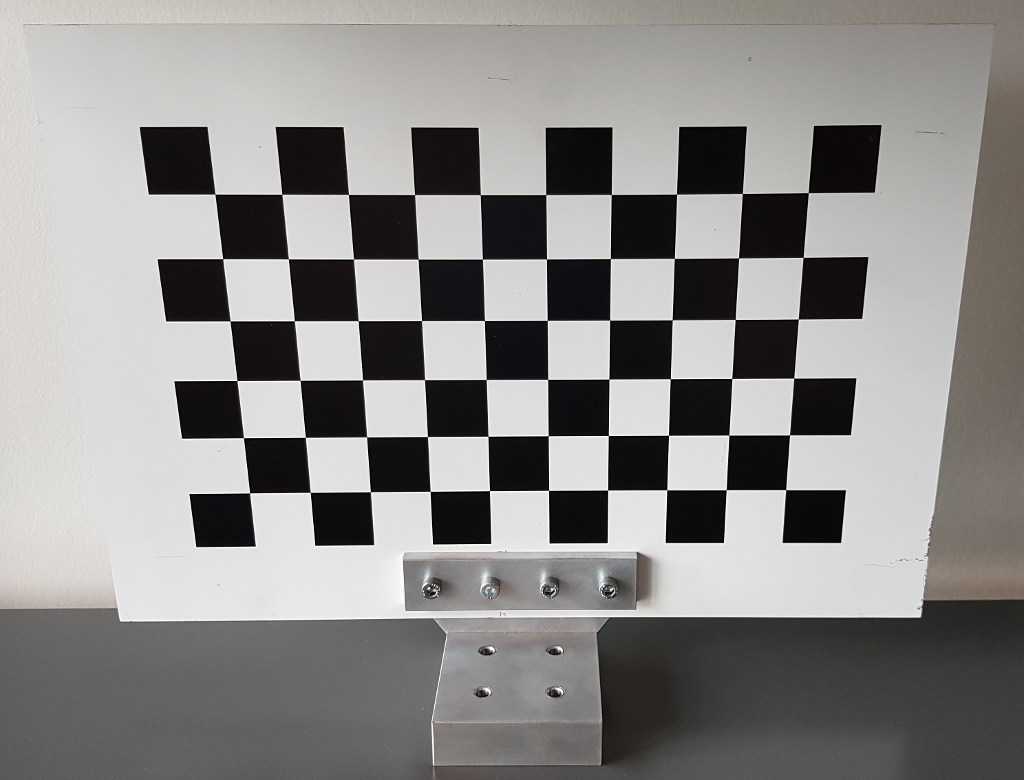
This calibration process needs a calibration checkerboard to calibrate the transformation between the robot's base and its arm base. It's a good practice to use a checkerboard gripper that can be screwed on top of the arm's gripper frame.
Preparation
To begin with, attach a checkerboard to the arm. Measure the translation of the reference corner of the checkerboard relative to the arm link it has been attached to. The reference frame should always be located at the second upper left corner as shown in the picture.
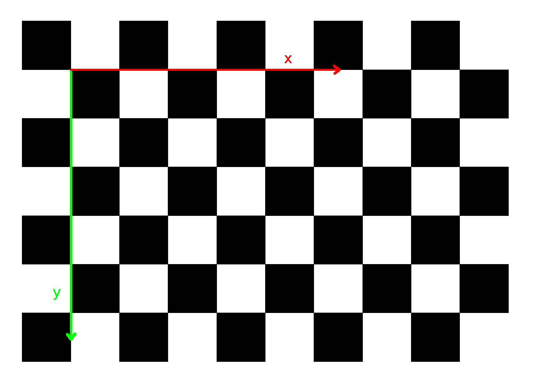
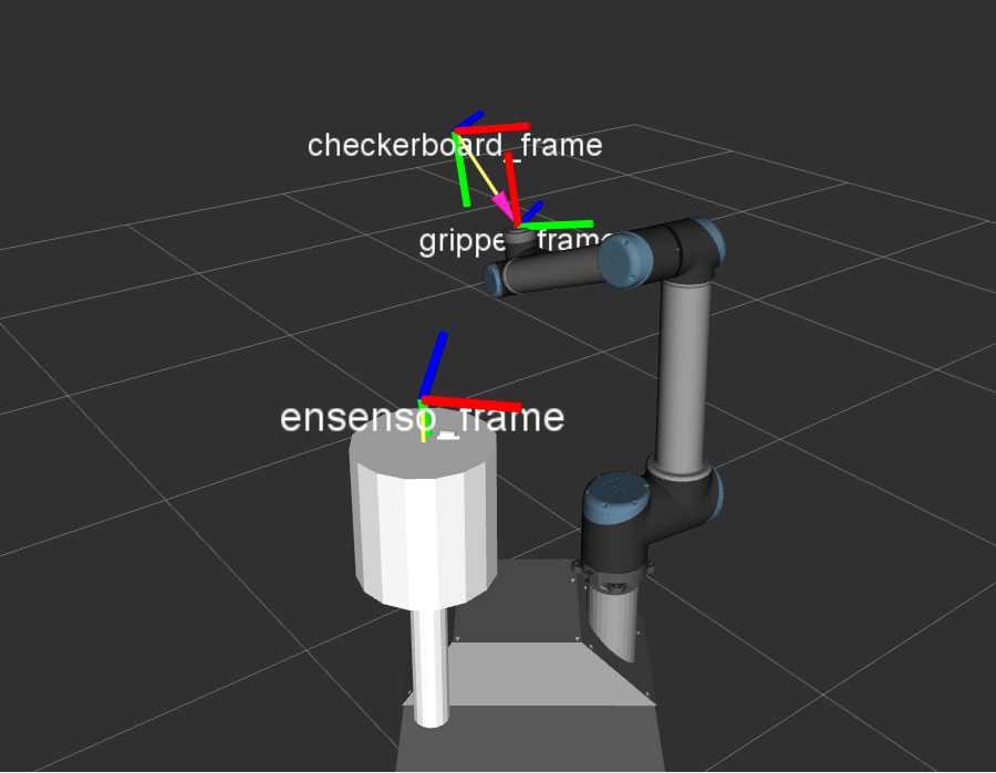
Also ensure that the checkerboard frame is aligned the same way as in the picture with x-axis (red) going from left to right and y-axis (green) pointing downwards. The z-axis is pointing into the plane. Make sure that the checkerboard transformation is available from TF, this can be done by adding it directly to the robot model or by using a static transform. By choosing the latter case you have to add the static transform to the arm_base_calibration.launch file before the arm_base_calibration node inside squirrel_calibration/robotino_calibration/ros/launch.
The following image illustrates an example setup for the RAW robot:
Afterwards, fill in the corresponding arm_base_calibration_params_Robotino.yaml file which is located in squirrel_calibration/robotino_calibration/ros/launch:
### checkerboard parameters
# side length of the chessboard squares
# double
chessboard_cell_size: 0.03

# Degrees of freedom of arm
# int
arm_dof: 6

# Degrees of freedom of camera
# int
camera_dof: 2

# number of checkerboard calibration points (in x- and y-direction), i.e. those points where 4 squares meet
chessboard_pattern_size: [10,6]

### initial values for transformation estimates
# insert the values as x, y, z, yaw (rot around z), pitch (rot around y'), roll (rot around x'')
# transform from base to first link of arm.
T_base_to_armbase_initial: [0, 0, 0, 0, 0, 0]

# the robot base frame [the transformation between laser scanner and base should be accomplished before, the transform from base_frame to armbase_frame will be calibrated by this program]
# string
base_frame: "base_link"

# arm frame attached to robot base
# string
armbase_frame: "arm_base_link"

# checkerboard frame attached to arm (2nd upper left corner) [the transformation between armbase and checkerboard_frame should be available from tf]
# this transformation is created in the arm_base_calibration.launch file.
# string
checkerboard_frame: "checkerboard_frame"

# this is the camera coordinate system which refers to the color image sensor [the transformations between base_frame and camera_optical_frame should be available from tf]
# string
camera_optical_frame: "kinect_rgb_optical_frame"

# Image topic
# string
camera_image_topic: "/camera/color_image"

# Topic to control camera postion
camera_joint_controller_command: "/torso/joint_group_position_controller/command"

# topic names for commanding the pan tilt unit
# string
# pan controller
pan_controller_command: "/pan_controller/command"

# tilt controller
tilt_controller_command: "/tilt_controller/command"

# Topic to control the arm joints.
# string
arm_joint_controller_command: "/arm_controller/joint_group_position_controller/command"

# pan state
# string
pan_joint_state_topic: "/pan_controller/state"

# tilt state
# string
tilt_joint_state_topic: "/tilt_controller/state"

# Topic to retrieve the current arm state
# string
arm_state_command: "/arm_controller/joint_states"

# storage folder that holds the calibration output
# string
calibration_storage_path: "~/.ros/robotino_calibration/calibration"

### program sequence
# loads calibration images and transforms from disk if set to true
# bool
load_images: false

# max allowed deviation a target angle is allowed to have in terms of the current joint angle [rad]
# double
max_angle_deviation: 3

# calibration interface ID. Decides which robot's interface to use: 0 - Robotino, 1 - RAW
# int
calibration_ID: 0
Capturing arm and camera positions for calibration
To facilitate the process of capturing arm and camera positions for the automatical calibration process you can use the jointstate_saver software provided in squirrel_robotino/jointstate_saver. The software settings can be adjusted to your needs using the saver.launch file inside the launch folder. The program can be launched by calling:
roslaunch jointstate_saver saver.launch
Ensure that the camera has clear sight to the checkerboard for each position change. It is recommended to also run the camera_calibration node alongside to ensure that each captured position is valid, meaning that all corners of the checkerboard can successfully be detected. It is important to take into account that the calibration routine will replay the same order of positions you capture. So avoid too large gaps in between two positions to avoid potential collision issues as the paths might not be planned. The results can be found in the ~/.ros/jointstate_saver/output folder. Copy the content of ArmJointStates and CameraJointStates and paste them inside the arm_base_calibration_params_Robotino.yaml file to the corresponding settings. Be aware that the more positions (~30) have been captured the better the calibration result will be. There are at least three positions for camera and arm needed for the software to run the calibration. (The following settings are example values only)
### checkerboard observation positions for capturing calibration images
# list of arm link configurations (angles per link in [rad]) for observing the checkerboard attached to robot's end effector
# includes <arm_dof> parameters per entry.
arm_configurations: [0,0,0,0,0,0,
                     0.1,0.2,0.3,0.4,0.3,0.2,
                     0,0,0.5,0.3,-0.2,0]

# list of camera link configurations (angles per link in [rad]) for observing the checkerboard attached to robot's end effector
# includes <camera_dof> parameters per entry.
camera_configurations: [0,0,
                        0.3,0.2
                        -0.1,0.3]
Starting the arm calibration routine
In order to start the process make sure that all settings in arm_base_calibration_params_Robotino.yaml are correct, ensure that the arm and camera have enough space to move and call afterwards:
roslaunch robotino_calibration arm_base_calibration.launch
The software will save an image of each position and all corresponding transformations for offline calibration (set load_images to true).
Transfer the calibrated values into the robot configuration
Replace these parameters in your squirrel_robotino/robotino_bringup/robots/xyz_robotino/urdf/properties.urdf.xacro file (example values):
  <!-- arm mount positions | handeye calibration | relative to base_link -->
  <property name="arm_base_x" value="0.323772"/>
  <property name="arm_base_y" value="-0.207722"/>
  <property name="arm_base_z" value="0.567751"/>
  <property name="arm_base_roll" value="-3.13495"/>
  <property name="arm_base_pitch" value="3.12087"/>
  <property name="arm_base_yaw" value="0.770357"/>
