Show EOL distros:
Package Summary
This package provides services to perform calculations related to the mild's kinematic model.
- Maintainer: Meißner Pascal <asr-ros AT lists.kit DOT edu>
- Author: Aumann Florian, Borella Jocelyn, Heller Florian, Meißner Pascal, Schleicher Ralf, Stöckle Patrick, Stroh Daniel, Trautmann Jeremias, Walter Milena, Wittenbeck Valerij
- License: BSD-derived
- Source: git https://github.com/asr-ros/asr_robot_model_services.git (branch: master)
Package Summary
This package provides services to perform calculations related to the mild's kinematic model.
- Maintainer: Meißner Pascal <asr-ros AT lists.kit DOT edu>
- Author: Aumann Florian, Borella Jocelyn, Heller Florian, Meißner Pascal, Schleicher Ralf, Stöckle Patrick, Stroh Daniel, Trautmann Jeremias, Walter Milena, Wittenbeck Valerij
- License: BSD-derived
- Source: git https://github.com/asr-ros/asr_robot_model_services.git (branch: melodic)

Contents
1. Description
This package provides services to perform calculations related to the mild's kinematic model.
It's main function is to solve the robot's inverse kinematics in different variations.
Furthermore, various utility functions related to the robot's kinematics are provided by it and can be accessed via ROS service calls or by directly implementing the package library.
2. Functionality
The package contains algorithms and functions to the following tasks:
2.1 Inverse Kinematics - with base movement
Solving the inverse kinematics represents the primary function of this package.
This means that, provided a target camera pose
(x, y, z, uw, ux, uy, uz)
a robot configuration
(x, y, alpha, ptu-pan, ptu-tilt)
- with x, y as the 2D position of the robot's base, alpha as the robot's rotation on the 2D map and pan, tilt as the angles of the PTU unit -
should be found, that moves the camera as close as possible to this requested pose.
Since the perfect solution for this problem can be ambiguous, two algorithms for solving this problem have been implemented.
2.1.1 Approximated solution
The approximated solution assumes both pan and tilt joint as well as the camera's center point to be at the same position in the kinematic chain.
Also, the position of this rotation point is assumed to be directly above the center of the robot's base.
Considering this simplified version of the kinematic chain, an optimization algorithm provided by the glpk package is used to find an optimal solution for pan and tilt angles, as well as the base rotation.
The calculated base position will trivially be equal to the x- and y-position of the target camera pose.
2.1.2 Exact geometrical solution
The exact geometrical algorithm uses the actual proportions of the kinematic chain to find an optimal solution for a requested camera pose.
Since in almost all cases, a camera pose can not be reached exactly by the robot due to restrictions in the kinematic chain, this algorithm will focus on bringing the camera into a pose that approximates the requested field of view as closely as possible.

The goal is to find a camera pose (and a corresponding view frustum - red), that faces the center of the target view frustum (black) in the same distance l while minimizing the angle deviation U0001d6ff as much as possible.
Using this optimization goal, an optimal robot configuration is calculated in two consecutive steps:
I - Finding optimal tilt angle and the tilt joint's pose in 3D-space
First of all, a set of assumptions will be made, that can be considered to be true about the mild's kinematic chain:
The distance of the ptu_base frame (/ptu_base_link) (and therefore the pan_base frame) to the ground plane is constant.
The rotational axis of the pan frame is orthogonal to the ground, which implicates that the distance of the tilt_base frame (/ptu_tilt_link) to the ground is constant as well.
- Therefore, both frames can only move within a defined plane parallel to the ground plane.
- Furthermore, the rotational axis of the tilt joint is assumed to be parallel to the ground plane.
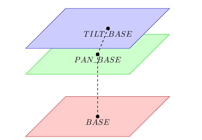
Using these assumptions, the optimization problem can reduced to a 2-dimentional geometrical calculation and the optimal position of the tilt joint on this plane and its corresponding angle can be calculated directly.
Let's consider a side view of the camera facing the target view frustum center, as well as the tilt joint (TILTED). Note, that the dotted horizontal line corresponds to the blue plane in the graphic above.
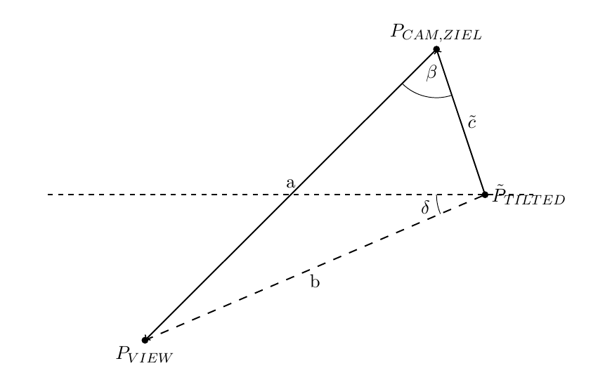
Given the position of the target view frustum center PView, the camera distance to the center a, the projected distance between tilt joint and camera center point c as well as the tilt joint's constant height above ground h, the tilt angle can be determined.
Once a solution for the tilt angle has been found, the position of PTilted can be calculated directly.
II - Calculating optimal pan angle and the corresponding base pose
Once an optimal pose for the tilt joint in 3D space has been determined, all that is left is to find a robot pose as well as a pan angle, that would place the tilt joint in that position.
However, the solution to this problem is not unambiguous, since the pan axis and the robot's base rotational axis are parallel and therefore create a mathematical singularity with an infinite number of possible robot configurations.
In this approach, this problem will be solved by sampling possible pan angles and selecting the one, that will result in the most convenient robot pose.
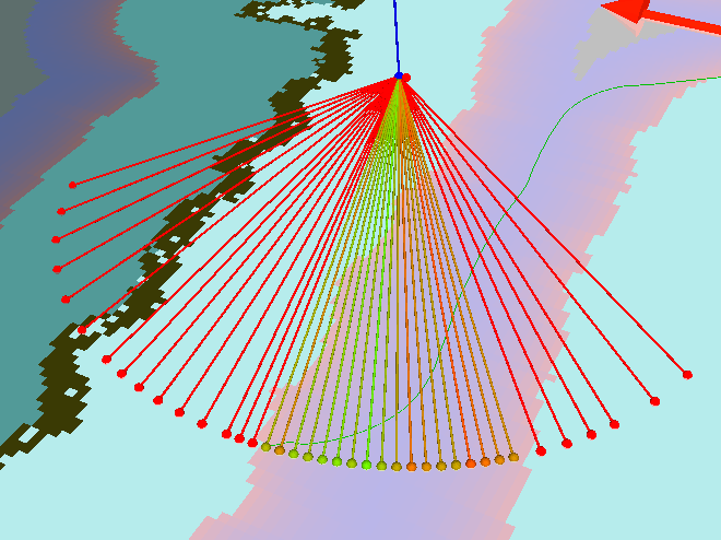
Visualized sampling of possible pan angles and the resulting position of the robot's base (small dots). Green dots are more favourable poses whereas non reachable or less favourable poses are displayed in red. Notice, that the robot's kinematic chain has been altered in this example, to show the criterias of selecting the best angle more clearly.
Several heuristics have been implemented to assess the feasibility of a given robot pose. Since rotations of the base are the most time consuming factor in this optimization process, all heuristics will focus on minimizing the those:
ANGLE_APPROXIMATION:
- This approach draws a straight line between the current robot position and the target position. It then sums up the absolute angle difference between the current orientation and this line as well as the line and the target robot orientation. The resulting value between 0° and 360° can be used to get a rough estimation of the traversed angle difference. However, this approach is only valid if the robot can reach the target pose in a roughly straight line. In a narrow space that includes a lot of obstacles, this heuristic might become imprecise.
NAVIGATION_PATH:
- This heuristic calculates the complete change of the base's orientation over the full path from the current base pose to the target pose. The absolute traversed angle difference of a path P will be calculated as:
 with α being the angle of the triangle defined by the three given points and x being the points defining the path P. This heuristic is the most exact one, however, since it requires the calculation of a complete navigation path, it is also the most perfomance-intensive one.
- This heuristic calculates the complete change of the base's orientation over the full path from the current base pose to the target pose. The absolute traversed angle difference of a path P will be calculated as:
SIMPLE:
- The simple heuristic compares the current orientation of the base with the target orientation and returns an absolute angle difference between 0° and 180°. The same restrictions as for (1.) apply here as well.
Result
The algorithm will return an optimal robot configuration, that would move the robot's camera into a pose with the same distance to the desired view frustums center and the least possible angle deviation from the desired view. However, if a requested camera pose is too far above or below the robot and therefore the view center point can not be focused by the camera within the optimal distance, no solution will be returned by the algorithm.
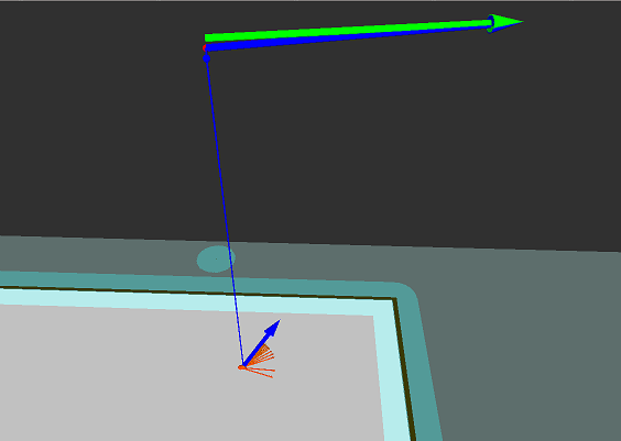
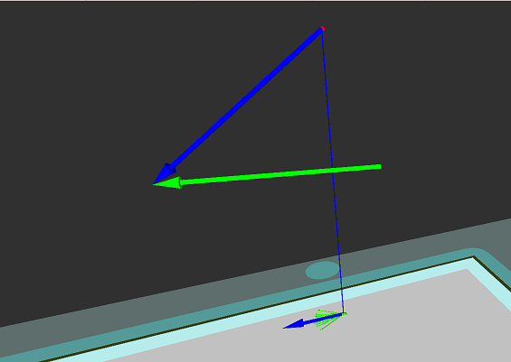
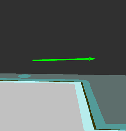
Requested camera poses (green) and approximated robot configurations (blue). Poses close to the camera's movement space can be approximated almost exactly (left), while poses below or above can only be roughly approximated (center). Poses too far above or below can not be approximated at all (right).
2.2 Inverse Kinematics - without base movement (PTU pose correction)
For some situations, it can preferable not to move the robot's base in order to reach a desired camera position but instead only try to find the optimal PTU angles
(ptu-pan, ptu-tilt)
to focus the camera on a target view point. Notice that this is only possible if the PTU angle restrictions allow moving to such a configuration and that an optimal distance of the camera to the target point can not be guaranteed.
A more detailed description of how this problem is being solve can be found here posecorrection.pdf.
2.3 Miscellaneous utility functions
Other utitlity functions provided by this package include calculation of the camera pose from a robot configuration, measuring the length of a navigation path between two robot poses and checking, whether a point on the map can be reached by the robot.
3. Usage
3.1. Needed packages
3.2. Needed software
3.3. Start system
Starting the RobotModelService for the real robot model:
launch asr_robot_model_services RobotModelServiceReal.launch
Starting the RobotModelService for the simulated robot model:
launch asr_robot_model_services RobotModelServiceSim.launch
Starting the set_focus_point script (see tutorial):
launch asr_robot_model_services set_focus_point.launch
4. ROS Nodes
4.1. Published Topics
- /nbv/frustum_marker_array
- message type: visualization_msgs/MarkerArray
- description: publishes the frustum visualization
- /nbv/object_normals
- message type: visualization_msgs/MarkerArray
- description: publishes the object normals
- /nbv/object_meshes
- message type: visualization_msgs/MarkerArray
- description: publishes all hypotheses with textures
- /nbv/frustum_object_meshes
- message type: visualization_msgs/MarkerArray
- description: publishes all hypotheses in the frustum
4.2. Parameters
robot_model_service_settings_sim/_real.yaml:
This file specifies general settings for the robot model as well as debug options
Omega-Factors: These values are only used for the approximated calculation of the inverse kinematic. Each factor declares, how favourable it is to reach a pose by moving the respective part of the robot. The higher a factor is, the more will the algorithm try to avoid the respective movement.
mOmegaPan: affects movement of the pan joint
mOmegaTilt: affects movement of the tilt joint
mOmegaRot: affects rotational movements of the robot's base
mOmegaBase: affects translational movements of the robot's base
mSigma: When calculating movement costs, the translational movement costs will be specified as
 with mSigma defining the steepness of the resulting function.
 tolerance: Used for the global planner. This value affects how tolerant the planner will be when navigating around the map.
useGlobalPlanner: Whether the global planner will be used to calculate a path for every possible solution of the inverse kinematic. If enabled, the calculation might be more precise, although this is performance intensive. If disabled, the euclidean distance will be used instead of the exact path.
ncp: Near-Clipping-Plane. Distance of the closest point, that can still be recognized to the camera.
fcp: Far-Clipping-Plane. Distance of the farthest point, that can still be recognized to the camera.
- visualizeIK: If true, the results of the exact inverse kinematics as well as the pose correction will be visualized (using the the topic specified as IKVisualization parameter). Should only be used for debugging, since the additional visualization adds additional performance overhead.
IKAngleApproximation: The heuristic algorithm used to determine the best solution for the mild's base's rotation during the calculation of the exact inverse kinematic. Options are:
- ANGLE_APPROXIMATION: Uses a straight line between the robot's current position and its target position. Calculates both the angle between the robot's current orientation and this line as well as the angle between the line and the target orientation and uses the absolute sum of both angles as heuristic.
- NAVIGATION_PATH: Calculates the complete change of the base's orientation over the full path from current to target pose. Requires the use of the global planner to return feasible results.
- SIMPLE: Compares the current orientation of the base with the target orientation
robotModelId: Determines which algorithm should be used to solve the inverse kinematics problem. Options are:
- 1 - MILDRobotModelWithExactIK: Uses a geometrical approach to solve the tilt angle and the robot's head's pose. The pan angle and the robot's base pose is then calculated by sampling possible pan angles and choosing the most preferable solution according to a specified heuristic.
- 2 - MILDRobotModelWithApproximatedIK: Uses an optimization algorithm to approximate an optimal solution.
PTU angle limits: All angles are specified in degrees, with the robot's initial position as pan=0, tilt=0.
- panMin
- panMax
- tiltMin
- tiltMax
colThresh: Collission threshold, that determines if the robot is colliding with an obstacle. Only used for the isPositionAllowed service call.
panAngleSamplingStepsPerIteration: Used for the exact inverse kinematic's angle iteration. This value specifies the number of sampling angles used per iteration.
inverseKinematicIterationAccuracy: A threshold used for the exact inverse kinematic's angle iteration. The sampling will stop after the angle change, compared to the previous iteration, is smaller than this value.
debugLevels: Specifies which debug messages should be displayed.
TopicsConfig.yaml:
This file specifies topic names, to which results will be published
IKVisualization: Topic, to which the visualization objects of the inverse kinematics will be published
robot_model_frames.yaml:
This file specifies the names of key frames in the robot's kinematic chain. See asr_mild_kinematic_chain for an overview over the mild's kinematic chain.
map_frame: Map base frame
base_frame: The mild's base frame
ptu_base_frame: The base frame of the PTU
ptu_pan_frame: The pan joint's frame
ptu_pan_frame_rotated: The pan joint's frame after rotation
ptu_tilt_frame: The tilt joint's frame
ptu_tilt_frame_rotated: The tilt joint's frame after rotation
camera_mount_frame: The mount frame for all cameras
camera_left_frame: The frame for the left camera
camera_right_frame: The frame for the right camera
4.3. Needed Services
(/move_base/make_plan): Provided by move_base , only needed if the option useGlobalPlanner is enabled.
4.4. Provided Services
CalculateCameraPose:
- Returns the pose of the camera's base frame in the world using the provided robot state.
- Input:
- sourceRobotState: the robot's state
- Output:
- cameraFrame: the camera's base frame
CalculateCameraPoseCorrection:
- Tries to find a PTU configuration that makes the robot's cameras as close as possible to a defined camera pose without moving the robot's base.
- Input:
- sourceRobotState: the robot's state
- position: the camera position which should be approximated
- orientation: the camera orientation which should be approximated
- Output:
- pan: the target pan angle
- tilt: the target tilt angle
GetCameraPose:
- Returns the 3-dimensional pose of the robot's camera frame.
- output:
- pose: the pose of the robot's camera base frame
GetDistance :
- Calculates the length of the path, which the robot would need to drive in order to get from one position to the other. Depending on whether the option useGlobalPlanner is enabled, this can either be the euclidean distance or the distance of an actual navigation path.
- Input:
- sourcePosition: the position from where the robot should drive
- targetPosition: the position to where the robot should drive
- Output:
- distance: the path distance
GetRobotPose:
- Returns the 3-dimensional pose of the robot's base frame.
- Output:
- pose: the pose of the robot's base frame
IsPositionAllowed:
- Checks if a given position is reachable for the robot.
- Input:
- sourceRobotState: the position to check
- Output:
- isAllowed: true, if the position can be reached
5. Tutorials
6. References
The functionality for the pose correction is described here: posecorrection.pdf
