Only released in EOL distros:
Package Summary
The BTA ROS driver
- Maintainer: Voxel Interactive <office AT voxel DOT at>
- Author: Angel Merino <amerino AT voxel DOT at>, Simon Vogl <simon AT voxel DOT at>
- License: MIT
- Bug / feature tracker: https://github.com/voxel-dot-at/bta_ros/issues
- Source: git https://github.com/voxel-dot-at/bta_ros.git (branch: master)
Package Summary
The BTA ROS driver
- Maintainer status: end-of-life (Moved to bta_tof_driver)
- Maintainer: Voxel Interactive <office AT voxel DOT at>
- Author: Angel Merino <amerino AT voxel DOT at>, Simon Vogl <simon AT voxel DOT at>
- License: MIT
- Bug / feature tracker: https://github.com/voxel-dot-at/bta_ros/issues
- Source: git https://github.com/voxel-dot-at/bta_ros.git (branch: master)
bta_ros
bta_ros package is set to end-of-life.
The package has changed its name to bta_tof_driver.
It will not be updated with the last changes. Please use bta_tof_driver instead of this package.
Contents
Summary
This driver allows to configure your system and ROS to use all Bluetechnix Time of Flight cameras supported by the BltToFApi. It includes some examples allowing you to visualize depth data using the rviz viewer included in ROS. It shows you how to use the ToF devices together with ROS and how you can modify operating parameters. Besides the ToF data, we have included a nodelet to capture rgb video from those devices that include a 2D sensor, such as the Argos 3D P320 or Sentis TOF P510.
First step: Get Ros
The 'bta_ros' works with ROS versions hydro, indigo and jade. You can use catkin workspaces or the older rosbuild to configure, compile the driver.
The following ROS tutorial links describe how to get ros_$ROS_DISTRO and a catkin workspace.
In Ubuntu: Follow the ROS installation tutorial:
http://wiki.ros.org/$ROS_DISTRO/Installation/Ubuntu
Install catkin if needed:
http://wiki.ros.org/catkin_or_rosbuild
http://wiki.ros.org/catkin/Tutorials/create_a_workspace
To configure a catkin workspace in your ROS installation, follow these:
ROS tutorial: http://wiki.ros.org/ROS/Tutorials/InstallingandConfiguringROSEnvironment
Known Problems
This is a release candidate
Getting the Bluetechnix 'Time of Flight' API
The BltToFApi is provided and maintained by Bluetechnix. The compiled libraries are on the support CD of your camera, or you can get if from:
https://support.bluetechnix.at/wiki/Bluetechnix_ToF_API_v2
It supports now the last released version of the api (v2.1.0). Move the library and the header to the bta_ros directory. You could install the library and its headers in the system path i.e. "/usr/include" and "/usr/lib". Finally, you can modify the Findbta.cmake file and add your own paths.
Compiling the package
Install dependencies
Make sure you have the following ROS dependencies already installed (gstreamer is only needed if you want 2d camera support):
apt-get install ros-$ROS_DISTRO-camera-info-manager ros-$ROS_DISTRO-pcl-ros ros-$ROS_DISTRO-pcl-conversions ros-$ROS_DISTRO-perception-pcl gstreamer1.0-dev libgstreamer-plugins-base1.0-dev
Installing the package
Clone from repository: https://github.com/voxel-dot-at/bta_ros.git to the src/ folder in your catkin workspace. Now compile it with:
cd catkin_ws
source devel/setup.bash ## initialize search path to include local workspace
cd src/
git clone https://github.com/voxel-dot-at/bta_ros.git
cd ..
catkin_make
Select compiling options
Since version v2.1.0 we just need one library to manage all interfaces (usb, eth, tim-eth or uart) of the Bluetechnix tof sensors.
If your device includes a 2D rgb sensor, after installing the gstreamer dependencies, you have to use the flag 2DSENSOR for compiling the 2D node.
#Including 2D
catkin_make -D2DSENSOR=on
Usage
We have included some .launch files to help you to get the camera working in a very simple way. You have the possibility of capture tof data, rgb images or both at the same time. We coded this ROS driver to use the ROS parameter server and the dynamic_reconfiguration tools which let you change the camera configuration at startup and at runtime. We will explain you in the following lines how you can write your own configuration for connecting to your Bluetechnix ToF device. You can also run the package as a node or as standalone nodelet and set the camera configuration via command line.
Use roslaunch
To easily start using the bta_ros driver you can use one of the roslaunch files we have included. It will launch the ROS core, start the bta_ros driver and the device, load the parameter configuration, start the run-time reconfiguration gui and the ROS viewer rviz already configured to show the depth, amplitudes, 3d or/and rgb information captured by the ToF camera.
In order to execute it you have just to type one of the following:
#For eth interface devices:
roslaunch bta_ros node_tof_eth.launch # for depth+amplitudes
#or
roslaunch bta_ros node_tof_eth_3d.launch #for xyz cloud 3d coordinates + amplitudes

#For usb interface devices:
roslaunch bta_ros node_tof_usb.launch # for depth+amplitudes
#or
roslaunch bta_ros node_tof_usb_3d.launch #for xyz cloud 3d coordinates + amplitudes

#For tim-eth interface devices:
roslaunch bta_ros node_tof_eth.launch # for depth+amplitudes
#or
roslaunch bta_ros node_tof_eth_3d.launch #for xyz cloud 3d coordinates + amplitudes

#You can also run the driver as node or nodelet. The following examples are intended to eth devices. Modify them in needed for other devices.
roslaunch bta_ros nodelet_tof.launch #for running it as nodelet
#or
roslaunch bta_ros node_tof.launch #for running it as node
bta_ros will advertise the following topics:
/nodeName/tof_camera/image_raw for amplitudes data
/nodeName/tof_camera/compressedDeth for distances depth data
/nodeName/tof_camera/point_cloud_xyz with 3D coordinates
They will contain data depending on the selected frame mode of the camera (frameMode parameter):
BTA_FrameModeCurrentConfig = 0 #Keep the frame mode selected in the camera
BTA_FrameModeDistAmp = 1
BTA_FrameModeDistAmpFlags = 2
BTA_FrameModeXYZ = 3
BTA_FrameModeXYZAmp = 4
Writing a custom configuration to the parameter server
As we commented before, you can load the camera configuration to the parameter server. The launch files include, inside the tag "node", the tag "rosparam" in which you can indicate a file containing the server parameters for the tof sensor. We have include several the configuration files like "/launch/bta_ros_1.yaml". This last is an example with a default configuration values for the camera. You may modify these files or add yours to load your own configuration.
Almost all configuration options are those corresponding to the configuration object given for start the connection with the ToF camera. You also can set the integration time and the frame rate when starting the connection with the device.
We need to set the right device in the configuration file. The devices id's are located in the headers of the BltTofApi.
// Generic
BTA_DeviceTypeGenericEth = 0x0001,
BTA_DeviceTypeGenericP100 = 0x0002,
BTA_DeviceTypeGenericUart = 0x0003,
BTA_DeviceTypeGenericBltstream = 0x000f,

// Ethernet products
BTA_DeviceTypeArgos3dP310 = 0x9ba6,
BTA_DeviceTypeArgos3dP320 = 0xb320,
BTA_DeviceTypeSentisTofP510 = 0x5032,
BTA_DeviceTypeSentisTofM100 = 0xa9c1,
BTA_DeviceTypeTimUp19kS3Eth = 0x795c,
BTA_DeviceTypeSentisTofP509 = 0x4859,

// P100 products
BTA_DeviceTypeArgos3dP100 = 0xa3c4,
BTA_DeviceTypeTimUp19kS3Spartan6 = 0x13ab,

// UART products
BTA_DeviceTypeEPC610TofModule = 0x7a3d,
This is an example of the needed parameter for connecting to a Bluetechnix tof device with a network interface:
#Parameter server configuration for eth interface devices.
udpDataIpAddr: {
n1: 224,
n2: 0,
n3: 0,
n4: 1,
}
udpDataIpAddrLen: 4
udpDataPort: 10002

tcpDeviceIpAddr: {
n1: 192,
n2: 168,
n3: 0,
n4: 10,
}
tcpDeviceIpAddrLen: 4
tcpControlPort: 10001

deviceType: 1
For a device using the usb interface you do not need to include any network parameter:
#Parameter server configuration for usb interface devices.
frameMode: 2
verbosity: 5
deviceType: 2
These options correspond to the BltToFApi C configuration object used for starting the connection with the ToF camera. To get more information about the configuration parameters, please refer to the BltToFApi documentation:
https://support.bluetechnix.at/wiki/BltTofApi_Quick_Start_Guide
For the 2d stream we just need the http URL address where the camera is serving the .sdp file to start capturing video. Inside you sensor2D node you must include the following parameter:
<param name="2dURL" value="http://192.168.0.10/argos.sdp"/>
Displaying 3d data with rviz
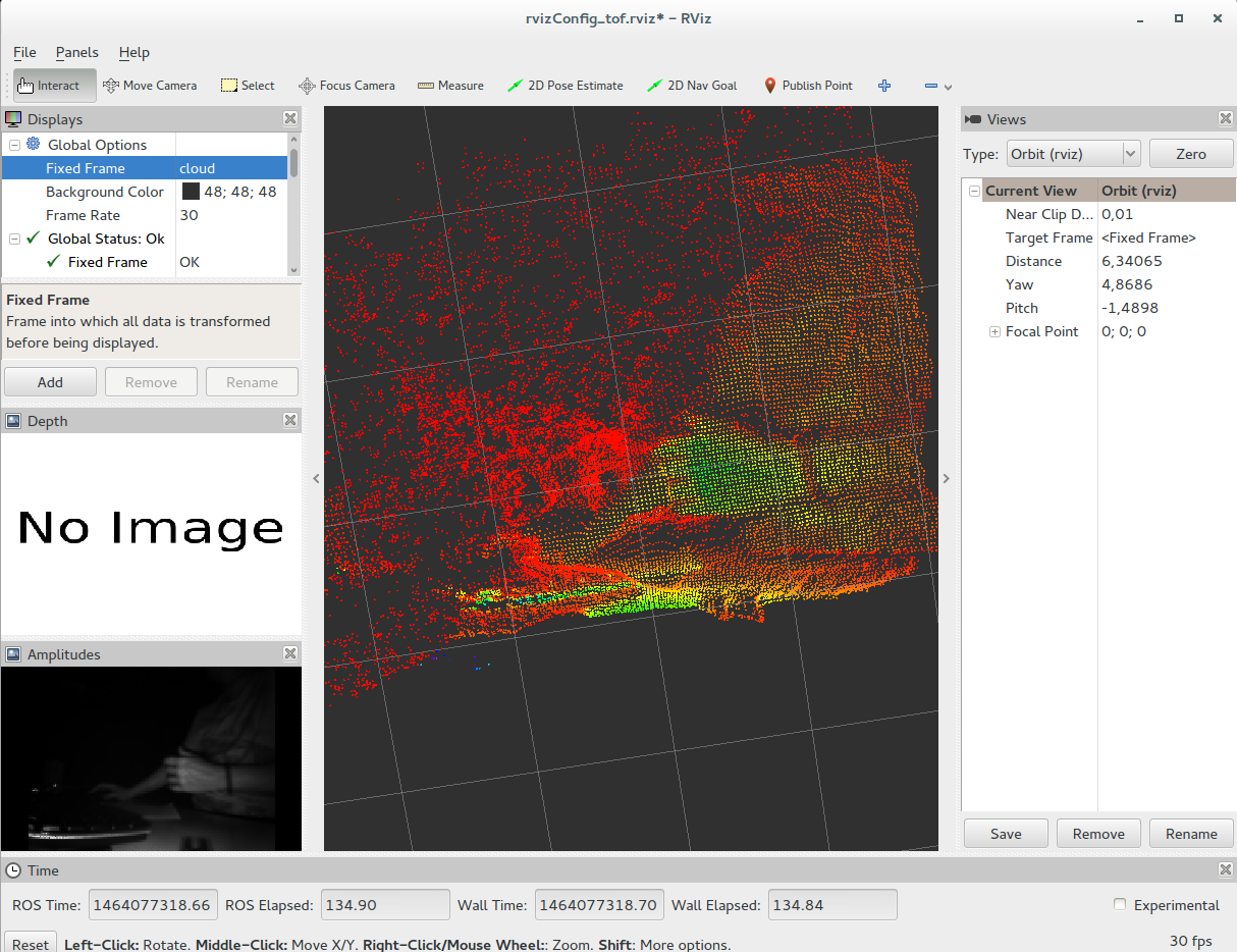
The Bluetechnix Tof sensor can provide 3d data in xyz coordinates. We just need to select the the right image mode to let the driver capture the 3d data and feed a ros topic with PCL PointCloud messages. See here.
We have included several config yaml and launch files that already select this mode and also open the ROS visualizer Rviz to display the 3d data.
#for xyz cloud 3d coordinates + amplitudes:

#Eth interface devices:
roslaunch bta_ros node_tof_eth_3d.launch

#Usb interface devices:
roslaunch bta_ros node_tof_usb_3d.launch

#Tim-eth interface devices:
roslaunch bta_ros node_tof_eth_3d.launch
The PointCloud transformation frame is published and it is connected to the world tf. That means, the world coordinates system, is the camera coordinates system.
In Rviz, you need to select the fixed frame of reference to show your cloud in the 3d space. Just select in Global Options->Fixed Frame the value cloud or world (drop down list).

It is also possible to get the xyz 3d coordinates using the calibration of the camera. You need to use the depth_image_proc node in the image_pipeline to reproject the depth image using the camera calibration. For we have include a camera calibration file (calib.yml) with the data from a Bluetechnix ToF camera with resolution 160x120 and the standard lens 90º field of view in the horizontal.
If you need to calibrate your camera yourself check camera_calibration node also in image_pipeline
Modifying camera parameters at runtime
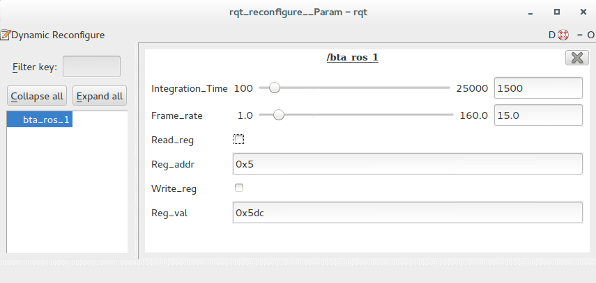
Using the dynamic_reconfigure package we can change the camera register to adapt the tof camera functions to our needs. We included different options for changing the integration time(Integration_Time) and the frame rate(Frame_Rate) as well as the possibility of read (Read_reg) and write(Write_reg) values to the camera registers(Reg_addr, Reg_val).

For using this option in an user interface, run the ROS rqt_reconfigure node or rqt_gui with the reconfigure plugin. We have included it to be run in the .launch files.
Manipulating Camera registers
In the rqt_reconfigure windows the boolean checkboxes "Read_reg" and "Write_reg" work as buttons to limit updates sent to the camera.
For reading you must set and register address through "Reg_addr" and then click on Read_reg. The result will be displayed in "Reg_val".
In case of writing a register just set the address "Reg_addr" and the value "Reg_val" and click on "Write_reg".
For any register operation an info message will inform you about it in the console.
Alternatively you can change the parameters via command line using dynparam from dynamic_reconfigure:
http://wiki.ros.org/dynamic_reconfigure
* Reading a register:
# 1. Set register address
rosrun dynamic_reconfigure dynparam set /bta_ros_1 Reg_addr 0x5
# 2.Run read
rosrun dynamic_reconfigure dynparam set /bta_ros_1 Read_reg True
The value will be displayed in console (in Reg_val ).
* Write a register:
# 1. Set_register_address
rosrun dynamic_reconfigure dynparam set /bta_ros_1 Reg_addr 0x5
# 2. Set register value
rosrun dynamic_reconfigure dynparam set /bta_ros_1 Reg_val 0x5dc #1500
# 3. Run write
rosrun dynamic_reconfigure dynparam set /bta_ros_1 Write_reg True
A console message will tell you if it was written correctly.
